Introduction
The front and rear Dacia Sandero car seats are points pressure welded.
In order to realize increased productivity and quality of a number of
devices fixing, monitoring and controlling the process it is needed.
Presentation of parts
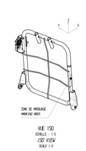
The rear seat backrest parts of the Dacia Sandero car by construction
point of view are made in three variants: RSB 40, RSB 60 and RSB 100. The paper
presents two types and sizes RSB 40 (Figure 1) and RSB 60 (Figure 2) of the car
seat backrest.
The building process consists of a metal frame that is welded pipe
clamps, hinges; reinforcement bar and wire mesh for an upholstery attachment.
Version RSB 40 require for preparing reinforced backrest execution of
12 welding seams on the front and 6 welds spot on the main axis of the tube and
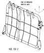
the execution of RSB 60 need 16 welding seams on the front and 12 points
welding on the main axis of the tube .
|
|
|
|
Fig. 1 Backrest
type RSB 40
|
Fig. 2 Backrest
type RSB 60
|
Manufacturing Technology
To achieve RSB 40 and RSB 60 backrests the following operations are
executed:
Open the valve on the compressed air column. Press the button next to the
gauge. Check this compressed air - 4 bar;
Valves are opened round-trip on
the cooling water supply columns and the welding tongs;
It is checked according to the
job with TPM (Total Productive Maintenance) of the post;
Run a sample for destructive testing;
If the result is consistent
(surrender shall be made by wire breakage) to begin the work. Otherwise, it must
inform the head of the team about results;
Put the preassembled backrest in
the prisms of the settlement ensuring that the device is correctly positioned;
Fix by pushing his left
pneumatic fasteners;
Place the back of the net for
40%, ensuring that it is positioned on aluminium and positioning the CEPI limits;
The net is fixed by pressing
left pneumatic seals;
Net frame welding will run. The
device will rotate as needed;
After taking the number of
points, the part is automatically released;
It is 100% visually check the
presence of 6 welding points and their position will be along the tube axis[1];
It is 100% visual checked of the
12 welding seams on the front of reinforcement;
The elimination part of the
device and 100% visually check the presence of 6 welded seams on the back of
reinforcement;
100% visual check concentricity
of the two nuts from the bracket holes;
Arrange the ensemble on the
support.
To be performed in the execution of welding operations device RSB 40
from Figure 3 and the fixture device RSB
60 of Figure 4 is used for the fixture.
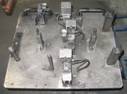
Fig. 3. Fixture
model RSB 40 - Rotating table and fixture for RSB40 B90 (Rear seat back 40, Dacia Renault project
B90 - Sandero)
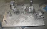
Fig. 4. Fixture
model RSB 60 Rotating table and fixture for RSB60 B90 (Rear seat back 60, Dacia Renault project
B90 - Sandero)
The process of welding for RSB60 and RSB40 types fittings will be
welding equipment TECNA3322 control unit having: TE300 and clamp arm length:
250mm (Figure 5) [2].
The parameters used are: Tolerance accepted: Current Intensity: + / -
200A, welding force: + / - 10%, welding pressure: + / - 0.5bari.
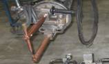
Fig. 5 Welding equipment.
In Table 1 welding parameters are showed. The main welding points were
the pressure P1 for model RSB 40 and P2 for model RSB 60.
Welding
parameters Table
|
No.
welding program
|
|
M.U
|
P1
|
P2
|
|
PRESSURE
|
|
bar
|
|
|
|
WELDING POWER
|
|
daN
|
|
|
|
BERTHING TIME
|
Param1
|
1/50
sec.
|
n/a
|
n/a
|
|
TIME PRESSURE
|
Param2
|
1/50
sec.
|
|
|
|
TIME PREHEATING
|
Param3
|
1/50
sec.
|
|
|
|
CURRENT PREHEATING
|
Param4
|
|
|
|
|
INTERIM PERIOD
|
Param5
|
1/50
sec.
|
|
|
|
GROWTH TIME
|
Param6
|
1/50
sec.
|
|
|
|
WELDING TIME
|
Param7
|
1/50
sec.
|
|
|
|
WELDING CURRENT
|
Param8
|
%
/ kA
|
|
|
|
NO. PULSES
|
Param9
|
itm
|
|
|
|
KEEPING TIME
|
Param10
|
1/50
sec.
|
|
|
|
WAITING TIME
|
Param11
|
1/50
sec.
|
|
|
Control system (anti-foul- poka-yoke)
Poka-yoke is the system which
controls the welding of the net frame for RSB40 and RSB60 backrest, this piece
is composed of the sensor in the fixture, pneumatic fastening device control,
connection cables, signal lamp, timer counting welded pressure points. If the
number of welding points and the track is not removed from the device, the
green light is shooting down and red lamp remains lit constantly. The gun is
locked and the display shows "unfinished piece".
If not given all the welds that must be given outside the device, in
the moment which is trying to start the new piece the gun is locked, lamps flash on and welder must
complete the unfinished piece.
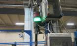
Fig.
6 Control
lamp for welding process
In Figure 6 is presented the control system. Poka yoke system is part
of the device for fixing reinforcement and count the number of pieces made, the
number of points and total points. For this system you can choose a specific
program for the case being examined. For this article the B90 program settings
were choose.
To achieve this control system there will be implemented additional
devices, which will be added to existing devices placed in the tube welding.
They will have the following functions:
They
allow a rotating-tilting movement between two positions - top position (100
degrees from the horizontal) to represent the position where the operator loads
the parts for welding device and a horizontal position (lid closed) to
represent the position of the welder;
Closure
of 'head' to the vertical position will be assisted by two gas strut
(gas piston), calculated to assist and not oppose the lifting of excessive
force in lowering the cap the maximum force will be established;
Newly
installed devices (caps) will contain a number of sensors equals to the number
of spot welds made in the device, allowing sensors to detect the upper
electrode clamp throughout the performance of each spot welds, all sensors will
be provided with protective elements to avoid mechanical damage to them through
contact with welding parts or accidental hitting. Sensors will be connected to
a "central" element installed on the cap, which will allow easier and fewer maintainability
of the wire connection of sensors and PLC station.
The design of the connections must take into account the movements and rotation
of the device and provide protection to ensure mechanical integrity and
electrical wires during handling[3];
Covers
will be provided with a closing / locking of the welding position. The horizontal
position will be checked by a sensor connected to the PLC station and covers
can be opened only on successful completion of all welds provided for that
operation;
Covers
will be provided with 'windows' to avoid interference with metal
fittings, wire mesh and structural elements of the current welding device, caps
will be provided with guides' points to ensure correct position for welding in
all welding set state.
Additional devices (caps) will be installed at these three positions:
Welding station B90 40% net to
the tube, where spot welds are made in June (RSB40);
Welding
mesh to the tube station B90 60%, are conducted 14 spot welds (RSB60).
Programming must include the relevant names as used for all programming
elements (inputs, outputs, bit memory functions). Use a TWDLCAA40DRF Twido PLC
and Magelis XBT Human Machine Interface type RT500.
Conclusions
Spot welding the valves seat pressure is a modern technology which
ensures a high quality joints. Due to the large number of points made there can
be missed some physical or welding points.
By implementing the new control system (poka yoke) the system will meet
the intended purpose of disposing of scraps and it will pass the validation
process for implementation in mass production. In addition the precise
positioning of the holes in the lid will be able to control and place in the
welded points.
Acknowledgements
"ACKNOWLEDGEMENT: This paper is supported by the Sectoral Operational
Programme Human Resources Development (SOP HRD), ID76945 financed from the
European Social Fund and by the Romanian Government
References
Georgescu, V.,
Mircea, O., et al.: Sudarea prin
presiune. Metode clasice (Pressure welding. Classical Methods). Brasov.
Lux Libris Publishing House, 2002.
Iovanas, R.: Sudarea electrica prin presiune (Pressure
electric welding). Timisoara. Sudura Publishing House, 2005
Joni, N. Trif,
I. N.: Sudarea robotizata cu arc electric (Robotic
arc welding . Brasov. Lux Libris Publishing House, 2005