Manipulation of nanoparticles
within a microfluidic system based on SU-8 polymer for bio-applications
CONTENTS
INTRODUCTON
FABRICATION
2.1. Microfluidic device
2.2. Preparation of solutions with magnetite nanoparticles
3.
CHARACTERIZATION
3.1. Characterization of the
magnetite samples
3.2. Characterization of the
microfluidic device
4. Simulation of fluid flow through the
microchannel
5. Conclusions
ABSTRACT
We present in this paper experimental results regarding
the control the fluid flow of aqua solution whit different nanoparticles such
as magnetite - Fe3O4, magnetite Fe3O4
- functionalized with silver particles, Fe3O4-functionalized
with gold particles, and gold nanoparticles by an array of Cr/Au electrodes in
a microfluidic system. The crystals of magnetite nanoparticles used in this
experiment, with particle size in the range of 10 nm, were synthesized by the
coprecipitation method from an aqueous Fe3+/Fe2+
solution. The microfluidic system was fabricated using SU-8 polymer and it
consists of an inlet, an outlet and a microfluidic channel with width of 200µm
control and length of 8250µm. The electrodes were configured on the bottom of
the microchannel. They are used to apply a small voltage on the solution in the
microchannel. The microfluidic system was characterized by optical microscopy,
white light interferometry and SEM (scanning electron microscope). We simulate
the distribution of the fluid velocity in the channel and we study the movement
of aqua solutions with different nanoparticles in the microfluidic system under
the influence of different voltages were applied, with different polarities.
1. INTRODUCTON
The use of
magnetic particles for isolation and preparation of bio-cells and proteins is
considered to be great interest in bioscience . The magnetite nanoparticles are attractive materials for
application in biomedical area such as diagnostic techniques, drugs, and
prostheses and implants. Interest is booming in biomedical applications for use
of nanoparticles in cell therapy (marking cells), cell biology (separation and
purification of cells populations), tissue repair, drug transport to the
affected area, and magnetic resonance . Among them, the magnetite (Fe3O4)
is one of the most suitable magnetic materials for bio-applications because it
has demonstrated a low toxicity and it is well tolerated by the human body. The
magnetite (Fe3O4) has an inverse spinel cube structure.
The oxygen atoms form a closed packing and iron cations occupy tetrahedron or
octahedral interstitial positions. Electrons can jump between ions Fe2+ and
Fe3+ in octahedral positions at room temperature [2-4]. The magnetite
nanoparticles were functionalized before being embedded with gold and silver.
In the aqueous solutions have been introduced different nanoparticles:
magnetite (Fe3O4), Fe3O4-Ag, Fe3O4-Au,
and gold nanoparticle. We simulated the liquid flow within the microchannel
using COMSOL multiphysics software, in order to determine the fluid velocity,
therefore the minimum debit of the microfluidic system. The flow was considered
to be laminar and incompressible. There were calculated the velocity and the
flux of the fluid flow under a pressure gradient of 20 Pa from the entrance
reservoir to the exit reservoir. The electrical behavior of the magnetite
samples under the influence of electric field produced by the electrodes inside
the microchannel was measured using an oscilloscope.
2.
FABRICATION
2.1.
Microfluidic device
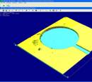
The microfluidic device was fabricated on p type
silicon wafer < >. First, an isolation oxide of 0.5µm layer was
thermally growth. After this, a 200nm thick layer of Cr/Au was deposited by
vacuum evaporation technique on the wafer. The electrodes were patterned using
photolithography and, subsequently, the Cr/Au was etched. The electrode shape
is that of a comb with the fingers (four) interdigitated with the opposite
electrode. The dimension of the electrode is 750µm with a space of 280µm
between them. A 30µm layer of SU-8 2050 polymer was deposited by spinning and
the microchannel with the two reservoirs was pat- terned using UV lithography.
It is well known that it is easy to obtain by lithography SU-8 microchannel
walls with high aspect ratio. In Fig. 1 is presented the fabricated
microfluidic device. The dimension of the reservoirs diameter is 200µm. The
microchannel length is 8520µm and the width is 200µm. These dimensions allows
an easily introduction of the magnetite solutions in the inlet reservoir and
the control of the fluids flow inside the microchannel.
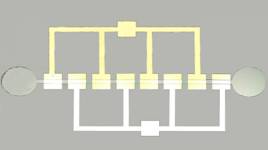
Fig.
1. Optical microscope picture of the microfluidic device.
2.2. Preparation of solutions with magnetite
nanoparticles
There is a wide range of methods for synthesizing
simple magnetite nanoparticles and functionalized magnetite nanoparticles with
precious metals such as silver and gold. We prepared for experiment three
solutions:
aqueous solution of magnetite
(Fe3O4) particles;
aqueous solution of Fe3O4-Ag;
aqueous solution of Fe3O4-Au.
The synthesis of magnetite particles was made by mixing
two solutions of FeCl2 and FeCl3 in the molar
concentration of 1:2. After that, droplets of ammonia solution with 1 molar
concentration were added at equal amount of time until it was achieved the
value 10 for pH of the solution. It is important to add constantly the ammonia
solution so the particle size to be uniform. By filtering this solution we
obtained the magnetite particles with dimensions mostly around 10 nm. These
particles were used further after functionalization in all solutions.
The magnetite solution was obtained by mixing magnetite
particles (5 g) with deionized water (10 ml). We used an ultrasonic
functionalized method for fabrication of the samples at temperatures of 80 C,
for 30 min. We functionalized the magnetite nanoparticles by adding
(3-glycidoxypropyl)trimethoxysilane (3GTMO) in aqueous solution. The role of
3GTMO is to serve as a "coupling agent" or "adhesion promoter" between the
magnetite nanoparticles and the features being embedded (gold and silver
particles).
The functionalized solution of magnetite particles (5
g) where mixed with aqueous solution with gold particles (10 ml-the molar
concentration of 1:10). Initially the silver particles were stored in a
solvent. Before using them, it was washed and diluted in deionized water (the
molar concentration of 1:10). The functionalized solution of magnetite
particles (5 g) where mixed with aqueous solution with silver particles (10
ml-the molar concentration of 1:10). Because of their applications in
biomedicine, the magnetic particles must present properties of biocompatibility
and stability in
aqueous
solutions. If the size distribution of the magnetic nanoparticle is very
narrow, an agglomeration of particles appears due to magnetization phenomenon
that occurs frequently in obtaining uniform magnetic fluids [11].
3. CHARACTERIZATION
3.1.
Characterization of the magnetite samples
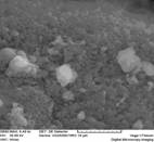
The characterization of simple or functionalized
magnetite samples was performed using the scanning electron microscope SEM. The
aqueous solution with nanoparticles was placed on the glass slide and, after
that placed in a controlled atmosphere, at room temperature to dry out. The
magnetite crystals sizes vary between 0.21 and 4.28µm. In Fig. 2 it can be seen SEM pictures for the other two types of
nanoparticles.
a)
 b)
b) 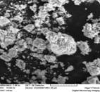 c)
c) 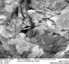
Fig.
2. SEM pictures of the magnetite crystals. (a) Crystals formed by
simple magnetite particles (Fe3O4); (b) crystals of
simple magnetite particles (Fe3O4) functionalized with
gold (Au) particles; (c) crystals of simple magnetite particles (Fe3O4)
functionalized with silver (Ag) particles.
The specific Fourier transform infrared spectroscopy
(FTIR) was done for magnetite particles and FTIR spectra are shown in Fig.
3. The samples for FTIR were prepared by grinding a quantity of the
sample with a specially purified salt (potassium bromide) finely (to remove
scattering effects from large crystals). This powder mixture is then crushed in
amechanical die press to form a translucent pellet through which the beam of
the spectrometer can pass. FTIR spectroscopy highlighted the specific spectrum
of magnetite wavenumber of 391.67 and 554.75cm
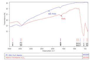
Fig. 3. Spectroscopy
FTIR for magnetite particles.
3.2.
Characterization of the microfluidic device.
The microfluidic device was characterized using a white
light interferometer (WLI) resulting the 3D profile of the whole device with
details in the reservoir area and in microchannel area and it is presented in
Fig. 4.WLI is used as a instrument for profilometry by measuring the centre of the axial signal response
from a surface
[12,13]. WLI can measure the position of the surface
to accuracies of up to 1 nm.
a)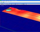 b)
b)
 c)
c)
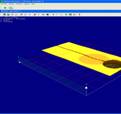
Fig. 4. 3D profile of the reservoirs and
the microchannel (without magnetite nanoparticles).
The 3D profile obtained by WLI gives the measured
parameters for the microfluidic systems as following: thickness of microchannel
layer is 34µm, reservoirs diameter is 1467µm and microchannel width is 224µm.
These values are in accordance with the designed values. In Fig. 5 are
presented 3D images of the device with the aqueous solution with magnetite
nanoparticles functionalized
with
gold particles. From this figure we determined the size of the simple magnetite
nanoparticles functionalized with gold particles to be 5µm.
a) b)
b)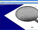
Fig. 5. 3D
profile of the reservoir and the microchannel with magnetite nanoparticles.
Different voltages were applied on the both electrodes
in order to analyze the behavior of the microfluidic system from electrical
point of view. The metals particles under the action
of an electric field generated by the current circulating in the electrodes
migrated in the aqueous solution in the channel from the inlet reservoir to the
outlet reservoir. If the polarization on the two electrodes is reversed, we
observed the movement of the particles in an opposite direction. Experiments
were realized with solutions containing magnetic particles functionalized with
silver and gold particles. The voltage values varied from 1.5 to 5V. The
particles migration started from 2.5 V. After testing the three types of
solutions, the best result was obtained for aqueous solution with magnetic
particles (Fe3O4) functionalized with gold particles (Au)
and it is represented in Fig. 6 the current-voltage characteristic in direct
and reverse polarization, directly on the oscilloscope screen.
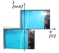
Fig. 6. Current-voltage characteristic of
the device with magnetite nanoparticles.
4.
Simulation of fluid flow through the microchannel
Fluid
flow through the microfluidic channel was performed using the specialized
simulation software COMSOL. The simu-lations were performed to determine the
velocity field of the fluid in absence of electrical field. To
determine this parameter is very important
because it is involved in determination of fluid
debit. In this simulation the flow was considered to be laminarn and incompressible. Therefore, the simulations were done
using the application mode "General laminar flow"
that uses the Navier-Stokes model for fluid
flow. The pressure at the inlet of the microchannel
was considered to be 20 Pa s. Since the concentration of the nanoparticles is very low we can consider that the
fluid in this simulation has physical
parameters of water, with a density of 1000
kg/m3 and the dynamic viscosity of 10 Pa
s.
Fig. 7 presents the simulation results for the
velocity field of the fluid in a section parallel
in the plane xOy. We can see a constant flow in the channel.
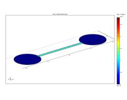
Fig. 7. Velocity field
in the microchannel.
Simulations of electrokinetic flow through a 2D
microchannel have been performed using the Electroosmotic Flow Mode of the
COMSOL simulation software. We considered in simulations a channel length of
8520µm and a channel width of 200µm. An electric potential of 2.5V is applied
on the electrodes placed under the microfluidic channel. A coupled domain
simulation has been performed. First it is solved the problem in the Conductive
Media Domain and the distribution of the electric field generated in the
microchannel is determined. Fig. 8 presents variation of the electric potential
along the microchannel after the activation of the electrodes.
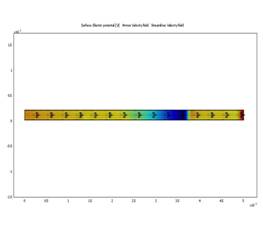
Fig. 8. Electric
potential along the microchannel after the activation of the electrodes.
The second step of the simulation consists in the
solving the Stokes Flow problem to determine the movement of the fluid through
the microchannel. Fig. 9 presents the velocity field in the channel under the
influence of the electric potential. The fluid that flowsthrough the
microfluidic channel is an aqueous solutions with suspended magnetic
nanoparticles. The simulation showed that the maximum value of the fluid
velocity in the channel is 1.53 mm/s.
a)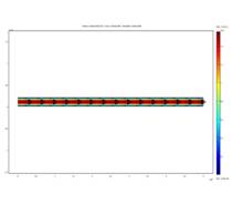 b)
b)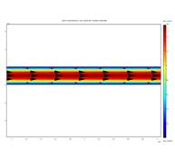
Fig. 9. Velocity
field in the microchannel under the influence of the electrostatic field: (a)
general view; (b) close up.
The
diffusivity of the suspended nanoparticles is 0.2 m2/s
and the concentration at the channel inlet is 0.1 mol/m3. Fig. 9
presents the velocity graph in the transversal section in the middle portion of
the channel (Fig. 10).
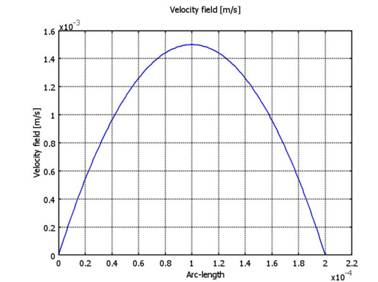
Fig.
10. Velocity of the fluid in the transversal section in the
middle portion of the channel.
5. Conclusions
Magnetite solutions functionalized with various metals
have been were prepared, characterized and tested. We manufacture a
microfluidic device using SU-8 polymer material and gold electrodes in order to
observe the behavior of the magnetite solutions. The magnetite nanoparticles
(simple or functionalized) in solution presented an agglomerations and formed
crystals with different sizes (SEM investigations). Special property of
magnetite fluids is a combination of normal liquid behavior and magnetic
control of position and flow. The microfluidic system was characterized with
different techniques: SEM, FTIR and white light interferometry. It was observed
that particles in aqueous solution have a controlled movement from the inlet
reservoir to the outlet reservoir, under direct or in reversed polarization.
The simulations of the liquid flow within the microchannel were performed using
COMSOL Multiphysics software, in order to calculate the fluid velocity. Due to
their physical, chemical, mechanical and thermal properties the nanoparticles
obtained we shall use our device in further work regarding bio-applications.
References
[1]
C. Rinaldi, T. Franklin, M. Zahn, T. Cader, Encyclopedia of Nanoscience and
Nanotechnology,
2004.
[2]
X.-C. Shen, X.-Z. Fang, Y.-H. Zhou, H. Liang, Chem. Lett. 11 (2004) 1468.
[3]
E.I. Friedmann, J. Wicrzchos, C. Ascaso, M. Winklhofer, Proc. Natl. Acad. Sci.
U.S.A.
98 (2001) 2176.
[4]
K.L. Thomas-Keprta, D.A. Bazylinscki, J.L. Kirschvink, S.J. Clemett, D.S.
McKAY, S.J. Wentworth, H. Vali, E.K. Gibson, C.S. Romanek, Geochim. Cosmochim.
Acta 64 (2000) 4049.
[5]
T. Schneider, L.R. Moore, Y. Jing, S. Haam, P.S. Williams, A.J. Fleischman, S.
Roy, J.J. Chalmers, M. Zborowski, J. Biochem. Biophys. Methods (2006) 68.
[6]
K.E. McCloskey, J. Chalmers, M. Zborowski, Anal. Chem. (2003) 75.
[7]
L.X. Tiefenauer, A. Tschirky, G. Kuhne, R. Andres, Magn. Reson. Imaging 14 (4)
(1996).
[8]
R. Kopelmana, Y.L. Koo, M. Philbert, B.A. Moffat, G.R. Reddy, P. McConville,
D.E. Hall, T.L. Chenevert, M.S. Bhojani, S.M. Buck, A. Rehentulla, B.D. Ross,
J. Magn. Magn. Mater. 293 (2005) 404.
[9]
J. Yang, S.-B. Park, H.-G. Yoon, Y.-M. Huh, S. Haam, Int. J. Pharma 324 (2006)
185.
[10]
V. Cabuil, Encyclopedia of Surface and Colloid Science, Marcel-Dekker Inc., New
York, 2002, pp. 4306.
[11]
A.S.G. Berry, J. Curtis, Phys. D.: Appl. Phys. (2003) 36.
[12]
B.S. Lee, T.C. Strand, Appl. Optics 29 (1990) 3784-3788.
[13]
T. Dresel, G. Häusler, H. Venzke, Appl. Optics 31 (7) (1992) 915-919.