Mecanisme de stocare
geologica a CO2
Cuprins
Introducere.
Prezentarea problemei
a.
b.
Stadiul la nivel international / national.
a. Platforme existente (scurta descriere)
b. Proiecte de cercetare : internationale, romanesti
i. CASTOR
ii. CO2 Club
iii. CO2 NET
Tipuri de (roci potential)
rezervoare geologice. Caracteristici.
Avantaje/dezavantaje. Capacitati de stocare.
Proprietati de transport ale CO2: densitate, vascozitate, solubilitate,
mobilitate, flotabilitate, miscibilitate
Mecanisme de stocare geologica a CO2 (fizica + chimica)
a.
Capcane
structurale, stratigrafice
b.
Dizolvare
c.
Saturatie
reziduala
d.
Precipitare/mineralizare
Particularitati ale stocarii geologice in formatiuni acvifere de adancime
a
b
Riscuri associate stocarii geologice a CO2
Concluzii
Bibliografie
Introducere. Prezentarea
problemei
a.
b.
Today the climate change issue has become a major
concern, and is perhaps one of the most
severe challenges of our time. Quick actions are required in order to
stabilise the global warming at 2-3
Centigrade within the 21st century. Although this elevated level
(to adapt to) results from the more optimistic trajectories in climate
modelling, it is still foreseen to have substantial
environmental impacts.
It
was first suggested by SINTEF (Erik Lindeberg) in 1986 to combine CO2
absorption techniques with geological storage of CO2 as a climate
change mitigation option. Since then, CCS
has become part of the scientific domain, and already spun off industrial actions merged with political influence and public awareness. Still substantial research and development
efforts are required in order to deem CCS viable on techno-economic terms.
Figure 1a - Évolution de la
consummation d'énergie mondiale en millions de tones d'équivalent pétrole.
Fig. 1b - Répartition de la
consummation d'énergie mondiale en 2003 en fonction des sources d'énergie.
Geological timelines in years
It can be seen from the
geological timeline that CO2 will be stored for a very long time, also in
comparison with the other geological processes that take millions of years.
Source: Stanley
(1999).
Age of the earth 4.6 billion (
Differentiation
Plate tectonic cycle
Formation of mountains
Formation of sedimentary
basins
Formation of fossil
fuels
Radioactive waste
CO2 storage
Reservoir production
lifetime <50
2. Stadiul la nivel international / national.
Platforme/proiecte de stocare existente (scurta descriere)
Proiecte de cercetare : internationale, romanesti
CASTOR
CO2 Club
CO2 NET
2.1
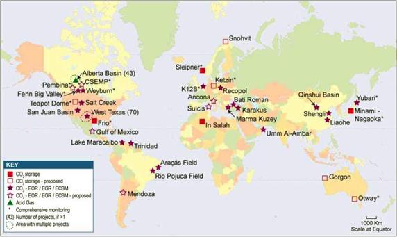
Examples of storage projects
Sleipner, North Sea (saline reservoir)
In-Salah, Algeria (gas
reservoir)
K12B, North
Sea (gas reservoir)
Weyburn, Canada
(oil reservoir)
Enhanced Coal Bed
Methane projects
Alisson (New Mexico)
Recopol (Poland)
Locations of CO2 storage activities
3. Tipuri de (roci potential) rezervoare
geologice. Caracteristici. Avantaje/dezavantaje. Capacitati de stocare.
In analiza formatiunilor geologice candidate ca rezervor pentru
stocarea CO2 se folosesc urmatoarele criterii de selectie:
a) distanta fata de sursa de CO2,
b) dimensiunea
rezervorului
c) caracteristici
geologice si hidrogeologice,
d) proprietatile
fluidului (din rezervor).
Din marea diversitate de formatiuni geologice,
doar trei sunt considerate optiuni de stocare a CO2 in subteran, pe
scara larga (figure 1): oil
and gas reservoirs, deep saline
aquifers, and coal beds. Fiecare
se caracterizeaza prin mecanisme fizice, care actioneaza la diverse scari de
timp, pentru distribuirea CO2 injectat in cadrul formatiunii si evolutia sa pe
termen lung.
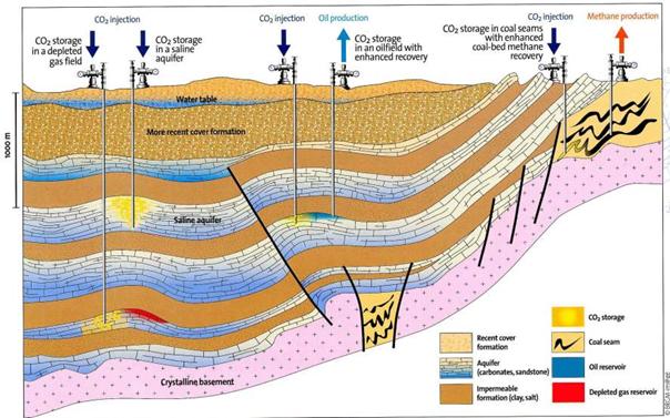
Bazinele
sedimentare sunt cele mai promitatoare sisteme geologice pentru stocarea CO2. Desi
cu raspandire larga pe suprafata pamantului, trebuie mentionat ca nu
intotdeauna sunt indeplinite conditiile de stocare. Exista diverse posibilitati
pentru stocarea geologica a CO2: campuri gazeifere epuizate, acvifere
sarate, zacaminte de petrol si strate de carbune, cu
varianta de recuperare suplimentara de gaze si petrol.
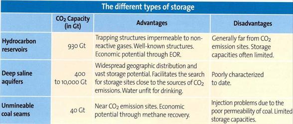
IEA, GHG, 2004
- Capacitate
de stocare potentiala


a These numbers would
increase by 25% if "undiscovered" oil and gas fields were included in this
assessment. Compare worldwide CO2
emissions: 25 GtCO2/yr.
Conform
datelor din tabel formatiunile acvifere sarate de adancime ofera capacitati de
stocare immense, atat comparativ cu celelalte optiuni de stocare cat si cu
emisiile de CO2 la nivel mondial.
Tipuri de medii geologice
Au fost identificate 5 formatiuni
geologice majore potential favorabile stocarii subterane a CO2: formatiuni
acvifere saline, strate de carbune, rezervoare de petrol si gaze,
sisturi, roci bazaltice.
a. Formatiuni acvifere sarate
Formatiunile acvifere sarate sunt reprezentate prin roci poroase-permeabile,
saturate cu saramuri si izolate prin una sau mai multe formatiuni
impermeabile cu extindere regionala care asigura captura CO2
injectat. Saramura
este o apa cu o concentratie foarte mare in saruri: de
regula TDS > 10,000 ppm. Au cea mai mare resursa potentiala de stocare.
b. Rezervoare de petrol si gaze
Sunt reprezentate de un strat de roci permeabile, in care se afla
petrolul/gazele si un strat de roci impermeabile deasupra care nu permite
migrarea fluidelor. Aceasta structura (capcana) geologica este principala caracteristica pentru stocarea pe termen
lung a CO2.
Ca
un avantaj suplimentar, injectarea de CO2 intr-o
astfel de structura poate creste cantitatea de petrol
recuperata. O parte din CO2 se va dizolva in
petrol avand ca efect cresterea volumului, scaderea
vascozitatii si favorizarea curgerii petrolului catre
forajele de exploatare.
In acest fel (EOR) se poate estima o crestere cu 10-15% a
factorului final de recuperare (30-40% in urma recuperarii primare si
secundare).
c. Strate de carbune
Toti
carbunii au cantitati variabile de metan adsorbit pe
suprafetele porilor. Pentru stratele de carbune neexploatabile se pot executa
foraje pentru recuperarea gazului metan (CBM). Metodele initiale
(conventionale) de recuperare a metanului, precum asecarea, scaderea
presiunii, lasa cantitati considerabile de metan in
formatiune. O recuperare suplimentara se
poate obtine prin injectarea de CO2. Functie de tipul de
carbune, intre 3 si 13 molecule de CO2 pot fi adsorbite pentru
fiecare molecula de metan eliberata. Astfel se asigura un excellent mediu de stocare a CO2 pe langa avantajele
economice ale recuperarii metanului (ECBM).
Atribute
cheie ale unui rezervor pentru stocarea CO2:
Injectivitate = Permeabilitate + grosime corespunzatoare
. poate fi
imbunatatita
- strategii de injectare (numar de
foraje, lungime tronsoane de injectie),
- stimulare (hidrofracturare).
. posibile influente ale
interactiunii CO2-roca-fluid asupra permeabilitatii
Capacitate de stocare = volumul corespunzator al porilor
accesibili; depinde de:
grosimea si extinderea formatiunii; porozitatea efectiva;
compresibilitate; heterogeneitate; gradul de saturatie al porilor cu CO2;
extinderea penei de CO2;
. Depinde/ este in stransa
legatura cu adancimea pe care sunt indeplinite conditiile
supercritice de stocare;
. Atentie la dizlocuirea si
deplasarea saramurii fara a induce efecte negative asupra mediului.
Izolarea / etansarea
Proprietati de etansare: bariera
capilara, bariera permeabila, bariera de presiune.
. Continuitate si grosime,
. Extindere geografica,
. Stabilitate geomecanica
. Stabilitate geochimica
. Absenta faliilor continue si conductive
. Evidenta forajelor abandonate
Probabil cel mai greu de caracterizat
Caracterizarea/descrierea site-ului trebuie sa
fie specifica tipului de stocare
Campuri petroliere/gazeifere epuizate
+ Injectivitate si capacitate bine stabilite
+ Capacitate dovedita de a retine/stoca
hidrocarburi
+ In general bine caracterizate
- Site-uri nu sunt intotdeauna disponibile la momentul
si la locatia dorita
Aspect important privind izolarea: posibile scurgeri/pierderi prin foraje
(cunoasterea forajelor abandonate, integritatea forajelor).
Formatiuni saline adanci
+ Cea mai mare capacitate de stocare
+ In general nu exista problema
competitiei cu o alta resursa, datorita
salinitatii foarte mari
- Incertitudini in estimarea injectivitatii
si capacitatii
- Izolarea/etansarea dificil de
caracterizat si demonstrate (ecran > 100 km2, etc)
- De regula informatii
disponibile limitate, necesare foraje noi, investigatii geofizice etc.
Aspect important privind izolarea: posibile scurgeri pe falii/fracture
(detectarea faliilor, caracteristicile faliilor, integritatea ecranului in timp).
Proprietati de transport ale CO2:
densitate, vascozitate, solubilitate, mobilitate,
flotabilitate, miscibilitate
In conditii normale
CO2 este un gaz termodinamic foarte stabil,
mai greu decat aerul (densitate 1.872 kg/m3 in conditii normale).
La temperaturi mai mari decat Tc=31.1°C si presiuni mai mari decat Pc=7.38
MPa (punctul critic), CO2 este in stare supercritica, cu o densitate
care creste, functie de presiune si temperatura, de la 150 la
> 800 kg/m3 , pentru
conditiile specifice bazinelor sedimentare. Daca se preconizeaza
injectarea de CO2 in formatiuni geologice adanci, atunci se pot
estima proprietatile
CO2 functie de conditiile tipice locatiei de
injectare.
Figure
2. Densitatea CO2 functie
de P si T.
Densitatea CO2 in functie
de T & p
Graficul prezinta
variatia densitatii cu adancimea, considerand presiunea
hidrostatica si un gradient geotermic 25°C/km
(de la 15°C la suprafata. Densitatea creste
rapid pana la aproximativ 800 m unde CO2 atinge starea supercritica.
 Cuburile
reprezinta volumul relativ ocupat de CO2 si, pana la 800 m se
observa scaderea dramatica a volumului cu adancimea. De la cca. 1.5 km, densitatea si volumul specific devin aproximativ constante. Cresterea
temperaturii la adancimi mai mari determina o densitate mai mica, in
vreme ce din cresterea presiunii rezulta o densitate mai mare.
Cuburile
reprezinta volumul relativ ocupat de CO2 si, pana la 800 m se
observa scaderea dramatica a volumului cu adancimea. De la cca. 1.5 km, densitatea si volumul specific devin aproximativ constante. Cresterea
temperaturii la adancimi mai mari determina o densitate mai mica, in
vreme ce din cresterea presiunii rezulta o densitate mai mare.
Flotabilitatea (buoyancy) - este o forta foarte puternica
ce depinde de temperatura si presiune prin variatia
densitatii. In conditii normale densitatea apei este aproximativ constanta
comparative cu densitatea CO2. Cu toate acestea apa ce
contine saruri si/sau CO2 este mai grea decat apa pura. In subteran CO2 are densitate mai mica decat a apei, astfel ca CO2
tinde sa se deplaseze ascendent. Acest efect va deveni mai puternic pe
parcursul migrarii ascendente deoarece reducerea presiunii determina
o scadere a densitatii. Pe de alta parte scaderea
temperaturii, la aceeasi presiune conduce la o densitate mai mare.
Aceasta dependenta este foarte puternica la temperaturi
si presiuni mici, asa cum este indicat de limita supercritica. In aceste conditii densitatea, la adancimea de 1 km, este in jur de
600 kg/m3.
La
temperaturi ridicate corespunde o vascozitate redusa, ceea ce
inseamna o rezistenta mai mica la curgere si deci o
injectie mai buna a CO2. In stare supercritica CO2 este mult mai
putin vascos decat apa si petrolul (cu cel putin un ordin de
marime), astfel ca exista un mare contrast de mobilitate intre CO2
si fluidele in situ din formatiune. In acest caz migrarea este
controlata de aceste fluide (Nordbotten et al., 2005a; Celia et al.,
2005).
Datorita
mobilitatii comparativ ridicate a CO2, doar o parte a apei si
petrolului va fi dizlocuita la injectarea CO2 is injected, in schimb o
mare parte va fi saturata cu CO2, cu o valoare medie de 30-60%. Procesul de viscous fingering apare in frontul CO2 injectat unde o parte
a CO2 dizlocuieste petrolul si apa iar o alta parte este saturat in
petrol si apa. Aceasta poate determina ca CO2 sa bypass mare
parte din spatiul poros, functie de heterogeneitatea si
anizotropia permeabilitatii (van der Meer, 1995; Ennis-King and
Paterson, 2001; Flett et al., 2005). Pentru rezervoarele de gaze naturale, CO2 este
mult mai vascos decat gazul in situ astfel ca "frontul" va fi stabil iar viscous
fingering limitata.
In saramuri solubilitatea CO2 scade pe
masura ce salinitatea creste (salting-out
effect).
 Din grafic se observa ca la p = 100 bari si T = 50 C, 50 kg de CO2 se pot dizolva intr-un volum de 1 m3 de apa. In
continuare, mai mult CO2 se poate dizolva in apa
si astfel stocat in acvifer, la temperaturi mai mici. Functie de conditiile
de presiune, temperatura si salinitate din acvifer circa 20-60 kg de CO2
pot fi dizolvate intr-un metru cub de apa. The red circle marks the area for underground CO2 storage. Atingerea echilibrului poate dura zeci de ani, pana la 100 de
ani.
Din grafic se observa ca la p = 100 bari si T = 50 C, 50 kg de CO2 se pot dizolva intr-un volum de 1 m3 de apa. In
continuare, mai mult CO2 se poate dizolva in apa
si astfel stocat in acvifer, la temperaturi mai mici. Functie de conditiile
de presiune, temperatura si salinitate din acvifer circa 20-60 kg de CO2
pot fi dizolvate intr-un metru cub de apa. The red circle marks the area for underground CO2 storage. Atingerea echilibrului poate dura zeci de ani, pana la 100 de
ani.
Gazul natural si CO2 sunt miscibile si formeaza o
singura faza fluida.
CO2 (lichid sau lichid in stare supercritica) si apa
sunt imiscibile (dar CO2 se poate dizolva in apa). CO2 si
petrolul sunt miscibile sau nemiscibile functie de compozitia petrolului
si conditiile termodinamice. CO2 and carbune: interactiune
foarte complex in care adsorbtia joaca un
rol important.
Proprietati ale CO2 injectat in stare
supercritica:
Miscibilitate redusa cu
saramura (limita de solubilitate ~ )
Densitate mai mica decat
saramura (raportul densitatilor 0.25-0.75)
vascozitate mai mica decat
saramura (raportul vascozitatilor 0.2 - 0.02)
Apa se poate evapora in CO2 (uscat)
Interactiuni CO2 - rezervor. Mecanisme
de imobilizare si stocare a CO2: fizica + chimica
a.
Capcane
structurale, stratigrafice
b.
Dizolvare
c.
Saturatie
reziduala
d.
Precipitare/mineralizare
Several mechanisms work in
combination to ensure that CO2 remains in the storage reservoir. Supercritical
CO2 is buoyant, and will migrate upward. This migration can be prevented by a
confining zone overlying the injection formation. Storage through this physical
trapping contains very high fractions of CO2, and acts immediately to limit
vertical CO2 migration. Capillary trapping can immobilize a substantial
fraction of CO2. This mechanism also acts immediately and is sustained over
long time scales. CO2 trapped this way may be considered permanently trapped. A
fraction of the CO2, will dissolve into other
pore fluids, including hydrocarbons (oil and gas) or brines. Depending on the
fluid composition and reservoir condition, this may occur rapidly (seconds to
minutes) or over a period of tens to hundreds of years. Over very long time
scales, much of the dissolved CO2 may react with minerals in the rock volume to
dissolve or precipitate new carbonate minerals, often called mineral
trapping. Precipitation of carbonate minerals permanently binds CO2 in the
subsurface; dissolution of minerals generally neutralizes carbonic acid species
and increases local pH, buffering the solutions and trapping CO2 as an ionic
species (usually bicarbonate) in the pore volume.
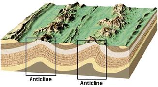
- Physical blocking by
- structural traps
(anticlines, unconformities or faults)
- stratigraphic
traps (change in type of rock layer)
Physical blocking by
structural and stratigraphic traps occurs only when CO2 is less dense than
reservoir fluid, so that fluid migrates upwards. Anticline is an arch shaped
fold in a rocks, closing upwards.
Unconformity trap is a
trap formed by a sealing formation, that has been
created by the folding, uplift and erosion of porous strata, followed by the
deposition of later beds that can act as a seal.
structural traps (folding and anticlines)
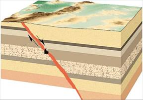
Faults
and unconformities
(Fault consists of different material)
Adsorption onto coal or
organic-rich shales: permanently reduced mobility
Mineralization into
carbonate mineral phases: permanently reduced mobility
Solubility trapping: CO2 dissolved in formation waters forming one single
phase:
greatly reduced mobility
Adsorption is the
attachment of an ion, molecule or compound to the (oppositely) charged surface
of a particle.
- Hydrodynamic trapping by
extremely slow migration rates of reservoir brine
- Residual gas trapping by
capillary forces in pore spaces
Residual Saturation Trapping
As CO2 migrates through the
formation, some of it is captured and permanently remained in the pore space,
which is referred to "residual CO2 trapping" (Obdam et al., 2003). When the
rate of this trapping is relatively high and CO2 is injected at the bottom of a
sufficiently thick formation, almost all of the injected CO2 can be trapped by
the mechanism before it reaches the surface boundary of the formation.
Likewise, the residual trapping mechanism plays a significant role in capturing
CO2 to be immobile.
From the simulation results (shown
in Figure 9), we can easily figure out that all of grid blocks which CO2 passes
though show residual gas saturation: the blue color indicates 0.2 of gas
saturation, which is the value of residual gas saturation, Sgr. Consequently,
this case represents quite similar trend of CO2 primarily-upward migration
compared with the base case due to isotropic condition; however, the explicit
difference is that CO2 cannot reach the upper surface of the reservoir.
- Negative buoyancy in case CO2 is denser than its host rock.
Following the injection of
anthropogenic CO2 below a typical depth of 800 m, the storage mechanism is
initially hydrodynamic as the CO2 is immobilized as a dense supercritical
fluid. On a separate timescale, and following the dissolution of CO2 in brine,
chemical interactions with the brine may form mineral carbonates [4]. CO2
reacts with brine's metal cations to form carbonate precipitates via the
following reaction sequence, in which selected likely precipitates are shown [5,6]:
CO2(g)fCO2(aq) (1)
CO2(aq)+H2OfH2CO3 (2a)
H2CO3fH++HCO3_ (2b)
CO2 (aq)+OH_fHCO3_ (3)
HCO3_fH++CO32_ (4)
Ca2++CO32_ fCaCO3 A (5a)
Mg2++CO32_f MgCO3 A
(5b)
Ca2++Mg2++2CO32_f CaMg(CO3)2 A (5c)
The dissolution of CO2 in water
(reaction 1) is dependent on temperature, pressure, and brine salinity.
Reactions 2a and 2b represent the formation of carbonic acid, which reduces the
pH of the system, and the dissociation of carbonic acid to form bicarbonate,
respectively. The bicarbonate ion may then dissociate (reaction 4) to form the
carbonate ion. The metals then react with the carbonate ion to form the
carbonate minerals in reactions 5a, 5b, and 5c, which are calcite, magnesite,
and dolomite, respectively.
The pH determines which steps
dominate the reaction sequence, and accordingly the proportions of the carbonic
species [5]. At a low pH (~4), the production of H2CO3 dominates, at a mid pH
(~6) HCO3_ production dominates, and at a high pH (~9) CO32_ dominates [6].
Therefore, at a basic pH the precipitation of carbonate minerals is favored because
of the availability of carbonate ions. Conversely, the dissolution of
carbonates increases as the solution becomes increasingly more acidic.
The rate of the mineral trapping
process is slow and serves as the major disadvantage of this technology [6]. In
the low to mid pH range, the rate limiting step of this reaction is the hydration
of CO2 to form carbonic acid in reaction 2a, which has a forward reaction rate constant
of 6.2_10_2 s_1 at 25 8C [7]. However, in the high pH range the rate limiting step
is the first dissociation of carbonic acid to form bicarbonate [6].
The parameters that affect the
efficiency of the carbonate forming process for both above and underground
sequestration operations are brine composition, temperature, pressure, and pH.
These parameters must be further understood since they determine both the
economic viability of the technology as well as help to identify locations that
favor sequestration.
Soong et al. [6] suggest that pH has
a significant effect on both conversion rates and on the specific species that
are precipitated. The formation of carbonates can thus be promoted by
increasing brine pH through the addition of a strong base. Their research qualitatively
identifies the effects of various parameters on carbonate precipitation. However,
pH evolution throughout the reaction is not documented.
Adequate containment of stored CO2
for sufficiently long periods of time (enough that it can be considered to be
safely removed from atmospheric circulation) is a critical part of any
assessment of potential for CO2 storage in the subsurface. CO2 can be stored by
a number of different trapping mechanisms, such as:
. Physical trapping in structural or
stratigraphic traps, where the free-phase CO2 is physically trapped by the
geometric arrangement of the reservoir and seal rock units (in a similar manner
to hydrocarbon accumulations, e.g. Biddle & Wielchowsky, 1994);
. Hydrodynamic trapping, where the
dissolved and immiscible CO2 travels with the formation water for very long
residence (migration) times (Bachu et al., 1994);
. Residual trapping, where the CO2
becomes trapped in the pore spaces by capillary pressure forces (Ennis-King
& Paterson, 2001; Holtz, 2002; Flett et al., 2005);
. Solubility trapping, where the CO2
dissolves into the formation water (Koide et al., 1992);
. Mineral trapping, where the CO2
precipitates as new carbonate minerals (Gunter et al., 1993); and
. Adsorption trapping, where the CO2
adsorbs onto the surface of the coal (Gunter et al., 1997a).
CO2 Trapping Mechanisms
The subsurface flow behaviour of
CO2, as well as the length of time involved, will influence the ultimate trapping
mechanism. There are a number of different trapping mechanisms for geological
storage of CO2, which include structural/stratigraphic trapping, hydrodynamic
trapping, residual trapping, solubility trapping, mineral trapping and
adsorption trapping. The following discussion is mostly extracted or modified
from Gibson-Poole (2008).
Structural/Stratigraphic Trapping
Structural/stratigraphic trapping
relates to the free-phase (immiscible) CO2 that is not dissolved in formation
water. When supercritical CO2 rises upwards by buoyancy it can be physically
trapped in a structural or stratigraphic trap (as a result of the CO2 being the
non-wetting phase) in exactly the same manner as a hydrocarbon accumulation.
The nature of the physical trap depends on the geometric arrangement of the
reservoir and seal units. Common structural traps include anticlinal folds or
tilted fault blocks (Figure 11a) and typical stratigraphic traps include those
created by a lateral change in facies up-dip or a depositional pinch-out
(Figure 11b). As with hydrocarbon accumulations, there are numerous variations
of structural and stratigraphic traps, plus combinations of both structural and
stratigraphic elements, that can provide physical traps for geological storage
of CO2. In a dipping formation with no defined structural closure, any small
bumps in the seal geometry will behave like small anticlinal structural traps
and free-phase CO2 will fill these to the spill point (due to buoyancy) before
migration continues (Bergman & Winter, 1995; Lindeberg, 1997; Ennis-King
& Paterson, 2002).
Hydrodynamic Trapping
In a storage project, supercritical CO2 will be injected as
a single phase, but once in the geological
formation it will partition into free-phase (immiscible) CO2 and a CO2-rich
brine. The flow of the freephase
CO2 is dependant on the dip of the sealing horizon and the
flow velocity and direction of the in situ formation water. In
horizontal or gently dipping reservoirs, this can lead to very long residence
times, of
the order of thousands to millions of years (Figure 12) (Bachu
et al., 1994). The dissolved CO2 will travel
with the moving formation water. Saline aquifers generally have
very low flow velocities, of the order of
tens of cm/year. This slow flow velocity leads to residence
times of millions of years. This geological timescale trapping of CO2 in deep
regional aquifers is called hydrodynamic trapping and avoids the need for structural
or stratigraphic traps (Bachu et al., 1994). This trapping mechanism can be
considered a 'rate
seal', as opposed to traditional 'rock seal' traps associated
with structural and stratigraphic traps.
Figure 12: Hydrodynamic trapping of CO2, where the CO2 migration
pathway is 10s to 100s km long
allowing for a long residence time.
Limited work on hydrodynamic
trapping for CO2 storage has been done in Australia. Notable are the studies
by Hennig et al. (2006) on the Showgrounds Aquifer at the Wunger Ridge site in Queensland and Henning
& Otto (2007) on the offshore Vlaming Sub-basin of Western Australia. During
the injection phase of a storage project (of the order of 20 to 40 years), the
migration of the CO2 away from the injection well involves both gravity
override and viscous fingering, as a result of the CO2 being significantly less
dense and less viscous than the saline formation water under typical reservoir conditions
(Ennis-King & Paterson, 2001; Nordbotten et al., 2005). Simulations by Holt
et al. (1995) determined that the rate at which the CO2 is injected can have an
impact on this displacement behaviour. At high injection rates, viscous forces
dominate and the CO2 plume develops rapidly along the most permeable paths. At
lower injection rates gravity forces dominate and buoyancy causes the CO2 to
rise upwards. The heterogeneity in the permeability distribution also has a
significant impact on the flow behaviour of injected CO2. If the degree of
heterogeneity is large, particularly with respect to the ratio between horizontal
and vertical permeability, then channelling of CO2 along the most permeable
paths will be the dominant flow behaviour (van der Meer, 1995; Ennis-King &
Paterson, 2001).
After cessation of injection,
migration of the CO2 plume continues during the relaxation of the pressure gradient
driving the lateral migration. The CO2 then continues to migrate under the
influence of gravity (or buoyancy) and the natural formation water flow
(Ennis-King & Paterson, 2001, 2002; Flett et al., 2003; Flett et al.,
2005). The dissolved CO2 moves with the formation water. The relationship
between these two phases determines which storage mechanism dominates and how
far the CO2 will migrate from the injection site before no free-phase, mobile
CO2 remains. The longer the migration pathway and the slower the migration
rate, the more CO2 will become trapped residually or in solution such that
eventually no mobile, free-phase CO2 will exist in the system, as modelled in
various numerical simulations, (McPherson & Cole, 2000; Ennis-King &
Paterson, 2005a). The length of the migration pathway is controlled by geological
parameters such as stratigraphic heterogeneities, for example, intraformational
siltstones, shales and coals, which play a crucial role in determining the
tortuosity of the CO2 flow path. The intraformational seals act as barriers or
baffles to the buoyancy-driven upward flow and induce lateral migration until
CO2 is able to breach the barrier or get past it (Ennis-King & Paterson,
2002; Hovorka et al., 2004; Flett et al., 2005). The flow velocities are
dependant on a number of factors, including the fluid properties (both freephase
CO2 and formation water), the mechanism of transport (diffusion, dispersion,
convection), buoyancy, rate of dissolution, the hydrodynamic drive and
direction, permeability, tortuosity, the impact of any geochemical reactions,
temperature (which affects viscosity and density), structural dip, relative permeability,
and so on.
Residual Trapping
Residual trapping occurs when the
CO2 becomes trapped in the pore space as a residual immobile phase by capillary
forces (Figure 13) (Ennis-King & Paterson, 2001; Flett et al., 2005). At
the tail of the migrating CO2 plume, imbibition processes are dominant as the
formation water (wetting-phase) imbibes behind the migrating CO2 (non-wetting
phase). When the concentration of the CO2 falls below a certain level it becomes
trapped by capillary pressure forces and ceases to flow (Ennis-King &
Paterson, 2001; Holtz, 2002; Flett et al., 2003; Flett et al., 2005).
Therefore, a trail of residual, immobile CO2 is left behind the plume as it migrates upward (Juanes et al., 2006). Residual CO2
saturation values vary between 5-30 % based on typical relative permeability
curves (Ennis-King & Paterson, 2001). Over time, the residually trapped CO2
dissolves into the formation water (Ennis-King & Paterson, 2001; Flett et
al., 2005).
Figure 13: Residual trapping of CO2
Solubility Trapping
Solubility trapping relates to the
CO2 dissolved into the formation water (Koide et al., 1992). Carbon dioxide
solubility increases with increasing pressure and decreases with increasing
temperature and water
salinity. Carbon dioxide may mix with, and then dissolve in,
formation water through the processes of diffusion, dispersion and convection.
Thus, time is an important factor in
the solubility trapping of CO2. With increasing time, more CO2 dissolves into
the formation water (Bachu et al., 1994; Ennis-King & Paterson, 2001). As
the CO2
continues to dissolve into the formation water, it can lead to a
phenomenon known as convective mixing.
The density of the CO2-saturated
water increases to become about 1 % more than that of the unsaturated
water when CO2 dissolves into the formation water. The dense
CO2-saturated water overlying less dense
unsaturated water creates a density instability and plumes of CO2-rich
water flow downward (Figure 14)
(Lindeberg & Wessel-Berg, 1997;
Ennis-King & Paterson, 2002; Lindeberg & Bergmo, 2003; Ennis-King
 & Paterson, 2005a). The time-scale for complete dissolution is critically
dependent on the vertical permeability and the geometry of the top seal, but is
predicted to occur on a scale of hundreds to thousands of years (Ennis-King
& Paterson, 2002). The success of solubility trapping is aided by slow flow
velocities of the in situ formation water, as this will lead to a
greater residence time and allow more time for CO2 to improve solubility
trapping, as they increase the tortuosity of the CO2 migration path and
accordingly the CO2 is able to contact larger volumes of formation water into
which it can dissolve (Lindeberg, 1997; Hovorka et al., 2004; Flett et al., 2005).
Convective mixing (resulting from density instability) is important for
solubility trapping of CO2, as it is orders of magnitude faster than pure
diffusion mechanisms, and so accelerates the overall dissolution of the CO2
into the formation water (Ennis-King & Paterson, 2002, 2005b).
& Paterson, 2005a). The time-scale for complete dissolution is critically
dependent on the vertical permeability and the geometry of the top seal, but is
predicted to occur on a scale of hundreds to thousands of years (Ennis-King
& Paterson, 2002). The success of solubility trapping is aided by slow flow
velocities of the in situ formation water, as this will lead to a
greater residence time and allow more time for CO2 to improve solubility
trapping, as they increase the tortuosity of the CO2 migration path and
accordingly the CO2 is able to contact larger volumes of formation water into
which it can dissolve (Lindeberg, 1997; Hovorka et al., 2004; Flett et al., 2005).
Convective mixing (resulting from density instability) is important for
solubility trapping of CO2, as it is orders of magnitude faster than pure
diffusion mechanisms, and so accelerates the overall dissolution of the CO2
into the formation water (Ennis-King & Paterson, 2002, 2005b).
Figure 14: Convective mixing of CO2:
example of a numerical simulation showing the high-density plumes of CO2-saturated
brine (grey colours) sinking into the brine column below (white colour) (kv/kh
= 0.01,
after 14400 years) (Ennis-King &
Paterson, 2005a).
Mineral Trapping
Mineral trapping results from the
precipitation of new carbonate minerals (Gunter et al., 1993). This storage
mechanism is the most permanent of the trapping types discussed as it renders
the CO2 immobile
(Bachu
et al., 1994, 1996). The time-scale
for mineral precipitation is typically long, of the order of tens to thousands
of years, depending on the initial minerals present (Perkins & Gunter,
1995; Kirste et al., 2004). Siliciclastic reservoirs are favoured over
carbonate reservoirs, in particular calcium-, magnesium- or ironrich siliciclastic
reservoirs, as they have the best potential for mineral trapping of CO2 (Gunter
et al., 1993; Bachu et al., 1994; Perkins & Gunter, 1995; Gunter et al.,
1997b).
The potential for mineral trapping
is quite variable from formation to formation and thus needs to be examined as
part of the site characterisation process for storage site selection. Mineral
trapping is a
function of the mineralogy of the reservoir rock, the chemical
composition of the formation water and the
formation temperature and pressure. In addition, potential reactions
depend on the contact surface
(interface)
between the mineral grains and the formation water containing dissolved CO2,
and on the flow
rate of fluids through the rock (Gunter et al., 2004). Due to
the specific information required to model
mineral storage of CO2, it is appropriate that it be undertaken as
part of site characterisation rather than
basin-scale assessment (CSLF, 2007). Detailed modelling of injection of
CO2 into the White Rim
Sandstone, Utah, using the reactive chemical simulator
ChemTOUGH, found that 1000 years after the 30
year injection period began approximately 21 % of the injected
CO2 was permanently stored as a mineral
and 52 % was free-phase gas or dissolved in the groundwater
(White et al., 2005b). As in residual and
solubility trapping, mineral trapping is a time-dependent process
operating on the scale of millennia (Bachu et al., 2007).
Storage Security for Saline/Hydrocarbon
Formations
In any geological storage site, the
injected CO2 will ultimately be trapped by a number of the mechanisms
described above. The type of trapping that occurs, and when, is
dependent on the dynamic flow behaviour
of the CO2 and the time-scale involved. With increasing time,
the dominant storage mechanism will change and typically the storage security
also increases. Figure 15 is a simple representation of CO2 storage and how the
trapping mechanism might alter over time. For example, the initial storage
mechanism will dominantly be physical structural and stratigraphic trapping of
the immiscible-phase CO2. With increasing time and migration, more CO2 is
trapped residually in the pore space or is dissolved in the formation water, increasing
the storage security. Finally, mineral trapping may occur by precipitation of
carbonate minerals after geochemical reaction of the dissolved CO2 with the
host rock mineralogy, permanently trapping the CO2 (IPCC, 2005).
Figure 15: Schematic representation of the change of
dominant trapping mechanisms and increasing CO2
storage security with time (from IPCC, 2005).
6.
Particularitati ale stocarii geologice in formatiuni acvifere de adancime
a
b
Deep
Saline Formations are layers of porous rock that are
saturated with brine. They are much more extensive than coal seams or oil- and
gas-bearing rock, and represent an enormous potential for CO2 geologic storage.
However, much less is known about saline formations because they lack the
characterization experience that industry has acquired through resource
recovery from oil and gas reservoirs and coal seams. Therefore, there is a
greater amount of uncertainty regarding the suitability of saline formations
for CO2 storage.
Saline formations are deep porous
sedimentary rocks saturated with formation waters that are considered unsuitable
for human consumption or agricultural or industrial use. They have been
identified by many studies as one of the best potential options for large
volume geological storage of CO2 (e.g. Bachu, 2000; Bradshaw et al., 2002).
Supercritical CO2 can be effectively stored in deep saline formations because
of its high density and high solubility in formation water at the relatively
high formation pressures encountered.
However, these formations are
commonly less understood (in comparison to shallow freshwater aquifers or hydrocarbon
bearing reservoirs) and any assessment of their CO2 storage potential typically
includes significant uncertainty because of the lack or scarcity of subsurface
data. In addition, the containment potential of the seal rock is usually
untested and there is uncertainty regarding potential for undiscovered natural
resources. However, their main advantages are that they are distributed widely
over the world and their potential storage capacity is large (Koide et al.,
1992; Hendriks & Blok, 1993; Rigg et al., 2001; IPCC, 2005). CO2 can be
stored in saline formations by a number of different trapping mechanisms, including
structural/stratigraphic, hydrodynamic, residual, solubility and mineral
trapping (see Appendix A
for a detailed technical discussion on CO2 trapping
mechanisms).
Proprietati ale
geo-fluidelor
All rocks in the crust
contain fluids (water, oil, natural gas, CO2)
Transport of fluids
depends on: Density, Viscosity, Solvability, Miscibility
When CO2 is injected
into geological formations transport will take place, which depends on certain
properties of fluids already present in these formations and of the CO2 that is
injected. The most important parameters (density, viscosity, solvability and
miscibility) influencing transport will be described. After that the relation
of these mechanisms with CO2 storage will be explained.
Buoyancy and density: In
case there is a difference in density between two substances, either gas or
liquid, the substance with the lowest density will rise upwards.
Viscosity: The internal
resistance of a substance to flow when a stress is applied
Solvability: The ability
of a substance to go into solution
Miscibility: The ability
of different fluids (gases and liquids) to mix (a miscible fluid are those that
mix in any proportion).
Desired fluid properties
for CO2 storage
High
density
High
viscosity
High
solvability
High
miscibility
So: low temperature and high
pressure
To store CO2 it is
necessary to have a highly dense, viscous, solvable and miscible injection
fluid. The first is to prevent it from escaping upwards since a dense fluid
tense to descend. The efficiency of CO2 storage in
geological media, defined as the amount of CO2 stored per unit volume increases
with increasing CO2 density. A high viscosity of the injection fluid makes injection more
difficult, but on the other hand it prevents CO2 to escape from the reservoir.
Both solvability and miscibility also have to be high because when CO2 is
coupled with the in situ fluid already present in a reservoir rapid
escape from the reservoir is prevented again. On the other hand enhanced
recovery from oil and gas fields can only occur when there is no solvability
and miscibility. The actual trapping mechanisms are described in the next
slides.
CO2
trapping forms in aquifers (in ordinea crescatoare a importantei cu timpul)
Physical trapping
Dense supercritical CO2
phase (> 31°C at 73 bars)
Chemical trapping
Solubility trapping:
CO2(aq), HCO3-, CaHCO3+, MgHCO3+, NaHCO30, .
Mineral trapping: CaCO3
(calcite), FeCO3 (siderite), NaAlCO3(OH)2 (dawsonite),
The injected CO2 is
trapped in several forms: dense CO2 phase, dissolved form, mineral form. Depends on the brine chemistry (salinity and detailed chemistry),
the precise mineralogy, the pressure and the temperature. Chemical
trapping increases with time due to slow kinetics of mineral dissolution and
precipitation reactions. The balance with time of the CO2 trapping forms is the
result of complex interdependent thermodynamic, kinetic, flow and transport
processes.
Contribution of physical
and chemical trapping options over time
 Right after the
injection, structural and stratigraphic blocking contribute
most to the trapping of CO2. Although it is not included in this graph,
adsorption is also contributing significantly to CO2 trapping quickly after
injection, in case CO2 is injected into a coal seam. After 10 to 100 years
after injection has stopped this amount is for a large part replaced by
residual and solubility trapping. After a period of roughly 1000 to 10000 years
mineral trapping starts to contribute significantly. In time the change in
contribution of different trapping mechanisms results in an increased storage
security.
Right after the
injection, structural and stratigraphic blocking contribute
most to the trapping of CO2. Although it is not included in this graph,
adsorption is also contributing significantly to CO2 trapping quickly after
injection, in case CO2 is injected into a coal seam. After 10 to 100 years
after injection has stopped this amount is for a large part replaced by
residual and solubility trapping. After a period of roughly 1000 to 10000 years
mineral trapping starts to contribute significantly. In time the change in
contribution of different trapping mechanisms results in an increased storage
security.
Saline Formation CO2 Resource
Estimating
Background: Saline formations are composed of porous rock saturated with
brine and capped by one or more regionally extensive impermeable rock
formations enabling trapping of injected CO2. A saline formation assessed for
storage is defined as a porous and permeable body of rock containing water with
total dissolved solids (TDS) greater than 10,000 parts per million (ppm), which
can store large volumes of CO2. A saline formation can include more than one
named geologic formation or be defined as only part of a formation.
This saline formation storage
assessment includes the following assumptions: (1) saline formations are
heterogeneous and therefore under multiphase conditions; (2) only 20 to 80
percent of the area inventoried and 25 to 75 percent of the formation thickness
assessed would be occupied by CO2; and (3) the efficiency factor accounts for
net-to-effective porosity, areal displacement efficiency, vertical displacement
efficiency, gravity effects, and microscopic displacement efficiency.
Screening Criteria: Saline formations assessed for storage are restricted to
those meeting the following basic criteria for the storage: (1) pressure and
temperature conditions in the saline formation are adequate to keep the CO2 in
dense phase (liquid or supercritical); (2) a suitable seal is present to limit
vertical flow of the CO2 to the surface (caprock); and (3) a combination of
hydrogeologic conditions isolates the CO2 within the saline formation. These
criteria also apply to existing UIC and other regulations, and are relevant to
capacity assessment as well, but the criteria are first incorporated into
resource assessments.
Depths: The storage of CO2 in saline formations is limited to
sedimentary basins with vertical flow barriers and depth exceeding 800 meters.
Sedimentary basins include porous and permeable sandstone and carbonate rocks.
The 800-meter cutoff is an attempt to select a depth that reflects pressure and
temperature that yields high density liquid or supercritical CO2. This is
arbitrary and does not necessarily designate a lower limit of depth conducive
to CO2 storage. Several natural gas reservoirs exist at shallower depths; this
infers that CO2 gas may be stored at shallower depths but only at pressure and
temperatures most likely to sustain gas-phase CO2 density. Because of the large
difference in density between liquid-phase and gas-phase CO2, the additional
storage of shallow saline formations is not anticipated to provide any
substantial increase in resource estimates for Atlas II, but this could
be considered in a site-specific assessment.
Caprocks: All sedimentary rocks included in the saline formation
resource estimate must have caprocks (vertical seals) consisting of shale,
anhydrite, and evaporites. Thickness of these seals is not considered in this
assessment. For increasing confidence in a storage estimate (determining CO2
capacity) other criteria including seal effectiveness (e.g. salinity and
pressure above and below the caprock), minimum permeability, minimum threshold
capillary pressure, and fracture propagation pressure of a caprock should be
considered.
Injection Pressure
All geologic formations have a
threshold pore pressure that will begin to propagate a fracture within the
injection formation if exceeded. Some caprocks withstand this pressure and the
fracture terminates at the caprock. Many relatively thick shales
constrain the growth of a fracture; however, in addition to a threshold
fracture pressure, shales have a capillary pressure threshold that if exceeded,
will breech and allow an injected fluid to pass through it. Every formation
(reservoirs and caprocks) has a pressure threshold that must be included in
site-specific CO2 capacity estimates. However, this pressure constraint can be
managed during the planning and operation stages of development and should not
influence the CO2 resource estimate. A storage site with limited injection
and/or pore pressure may reduce the CO2 capacity, but due to the number of
injection wells required or length of pipeline, it may be economically the best
choice. Moreover, drilling more wells can reduce the injection pressure into
each well and keep reservoir pressure lower. Horizontal wells tend to have
lower injection pressure as compared to vertical wells. Additionally, similar
to natural gas storage, if regulations and economics are favorable, water
production wells can be used to reduce
pressure and increase capacity at a particular storage site.
Injectivity
The daily or annual rate of CO2 that
can be injected into a specific geologic formation is described or inferred by
the term "injectivity." Relatively low or high injectivity for a formation is
determined by the flow characteristics of the formation (e.g., pressure, permeability,
and thickness), the type and size of wellbore drilled, the type of completion, and
the number of wells.
No injectivity (zero) means there is
no injection rate under any circumstances and as such
a geologic formation without injectivity cannot be considered
a CO2 resource. However, a geologic formation with low injectivity that
provides a CO2 injection rate greater than zero does provide the opportunity to
store CO2 and is considered a CO2 resource.
For selecting and designing specific
storage sites, a minimum acceptable injection rate for a well is required to
meet the capture rate of CO2 emitted by the industrial site or utility.
For
example, if injectivity and storage for 1 million tons per year from an
industrial plant is desired for 30 years, the first step in selecting an
injection site is to find a geologic unit or group of units as close to the
emission site as feasible (to minimize transportation costs) that has adequate
CO2 resource of at least 30 million tons. This industrial plant would likely
have a budget (or economic limits) for capturing and storing CO2 on a per-ton
basis (e.g, $15/ton). One of the next steps is to establish the most affordable
means of injecting CO2 that does not exceed the $15/ton economic limit. One
single well that could inject at least 1 million tons per year might be the
least-cost option. However, if one well cannot provide this high rate of
injectivity, additional wells or more expensive well types and completions will
be considered.
INJECTIVITY
Injectivity describes the rate of
injection that can take place in a given well and reservoir. As indicated in
Table 9, injectivity is calculated based on a variety of data, including
effective thickness over the injection interval, reservoir permeability, bulk
connectivity, and reservoir pressure. The units of injectivity can vary with
the data source, and include m3/day/Pascal/m and barrels/day/psi/ft. Much of
the data exist for oil and gas fields, but would be available only on a limited
basis for other targets, such as saline formations.
However, conventional wells,
geophysical surveys, and core analysis would be able to provide reasonable
estimates of injectivity for a project. Crucially, the injectivity depends on
the interval of reservoir exposed to the wellbore; thus, injectivity may be
increased through drilling long-reach horizontal wells or increasing well
count. If there is damage to the reservoir at the wellbore that restricts
injectivity, a small hydraulic fracture or acid stimulation may be applied to
correct it.
The amount of data needed to
properly quantify injectivity may vary by site, but it is highly unlikely that
one well and a limited geological or geophysical survey could alone provide
enough data to prove a reservoir has the needed injectivity. In many commercial
applications, the degree of reservoir connectivity is not well understood for
many years. Empirical and theoretical approaches will be important and can
provide additional information and allow for consideration of multiple
scenarios. In many cases, injectivity
data from neighboring oil, gas, and water wells, plus
information from analogous reservoirs, can provide this information.
CAPACITY
Storage capacity is measured in
units of volume (standard cubic feet, barrels). Several parameters are used to
generate a capacity estimate, of which pore volume is the most important. Pore
volume is a bulk term based on effective formation thickness and porosity.
Estimates of pore volume can be derived from data generated through core
analysis, wireline logs, or geophysical surveys. In some cases, 3-D seismic
surveys may be combined with well data to estimate the formation porosity
(Saggaf et al. 2003; Bachrach
and Dutta 2004). Often, a hydrodynamic simulation is needed to
estimate overall storage capacity.
A second key parameter in capacity
estimates is the utilization factor, or the effective pore volume. This
is the fraction of the pore volume that would actually retain or store injected
CO2. Utilization factor is a function of the fluid already present in the
reservoir, and reservoir heterogeneity at all scales, ranging from pore-throat
diameters to kilometer-scale connectivity, unit architecture, and residual
phase (or capillary) trapping (Juanes et al. 2006; Ide et al. 2007). The
utilization factor is also a function of the development strategy and well
planning, such that capacity can be increased by more wells or better well
design. Utilization factors vary from site to site, and can range between 5 and
50 percent, although most are less than 25 percent. An important consideration
is that estimates of capacity are affected by reservoir heterogeneity, which
determines the shape of the CO2 plume. Reservoir pressure constraints also
affect the ultimate capacity of a reservoir.
Inherent in any discussion regarding
capacity are the assumptions about storage mechanisms. Capacity assessments for
saline formations sometimes assume or calculate a dissolved fraction of CO2 of
3-6 percent (Bachu and Adams 2003). In the case of a structural or
stratigraphic closure, a substantial fraction of the pore volume might be
filled with CO2 as a pure phase. Moreover, CO2 buoyancy may make it difficult
to store CO2 in a substantial fraction of the available pore space. Finally, it
may be extremely difficult to predict the amount of residual phase trapping
(capillary trapping) without extensive sampling and analysis, and this is a
focus of research efforts (Holtz and Bryant 2005). Site characterizations
should be used to estimate the volume that would be stored as a dissolved
phase, as a trapped residual phase, or as a trapped contiguous, buoyant phase
(these proportions will also affect effectiveness or storage integrity).
Statements of these assumptions would allow for easy updating of initial
capacity estimates once new data become available. In practical terms, analog
and empirical data sets should be considered for initial capacity estimates,
but further scientific understanding regarding trapping mechanism assumptions
is needed; this is an important area for additional research.
CO2 storage capacity is an estimate
of the amount of CO2 that can be stored in subsurface geologic formations.
Because of uncertainties inherent to subsurface evaluation, exact quantification
of geological properties is not possible and therefore storage capacity is
always at best an approximation of the amount of CO2 that can be stored.
Storage capacity estimates therefore rely on the integrity, skill and judgment
of the evaluator and are affected by the geological complexity, stage of
exploration or development, amount of existing storage and of available data.
Use of the definitions should sharpen the distinction between the various
classifications and provide more consistent reporting.
Factors
affecting CO2 storage capacity include the density of the CO2 at subsurface reservoir
conditions, the amount of interconnected pore volume of the reservoir rock and
the nature of the formation fluids. Due to the flow behaviour of CO2 in the
subsurface, not all potentially available pore volume of the reservoir will
become occupied during injection and migration, with flow preferentially
occurring either upward due to buoyancy forces or laterally below low
permeability zones (i.e. spreading out in thin layers beneath intraformational
seals or the regional top seal rather than filling the entire pore volume).
This can make CO2 storage capacity volumes difficult to calculate, particularly
in the reservoir rocks underlying defined structural or stratigraphic closures,
where much of the available rock pore volume can be bypassed by CO2 preferentially
utilising higher permeability zones (Gibson-Poole, 2008). The potential CO2
storage capacity should therefore be assessed in terms of available
interconnected pore space, accounting for factors such as injection rate, rate
of CO2 migration, the dip of the reservoir, the heterogeneity of the reservoir
and the potential for fill-to-spill structural closures encountered along the
migration path. In addition, long-term prospects for storage, including
residual trapping, dissolution into the formation water or mineral trapping
(formation of new minerals) can also be considered (especially for estimating
potential storage volume within deep saline formations) (Gibson-Poole, 2008).
Such issues are best addressed by building geological models and running
numerical flow simulations to test the importance of the various factors
inherent to each specific site. The numerical flow simulations can give a more
accurate assessment of how much of the available pore volume is actually used
(sweep efficiency) in each particular type of trapping (Gibson-Poole, 2008).
Methodology for Storage Capacity
Estimation in Saline Formations
DOE (2006) provides a relatively simple volumetric equation
for the calculation of CO2 storage capacity in saline formations (Equation 1 and
Table 1) based on the concept that CO2 occupies the pore space (or parts of it)
within a permeable rock:
GCO2 = A hg tot E (1)
Table 1:
Volumetric equation parameters for capacity calculation in saline formations
(from DOE, 2006).
The storage efficiency factor (E)
adjusts total gross thickness to net gross thickness, total area to net area and
total porosity to effective (interconnected) porosity actually containing CO2.
Without E, Equation 1 presents the Total Pore Volume or maximum upper limit to
capacity. Inclusion of E provides a means of estimating storage volume for a
basin or region with the level of knowledge (uncertainty) in specific parameters
determining the type of CO2 storage capacity estimated.
A reasonable maximum Prospective
Storage Volume may be estimated by assuming CO2 injection wells may be placed
regularly throughout the basin, or region, and multiplying the storage
efficiency terms in Table 2 together to determine the storage efficiency factor
for the basin or region. In Table 2, the first three terms An/At, hn/hg and
φe/φtot are used to define the regional effective pore volume, and
the next three terms EA, EI and Eg are used to define
the fraction of that volume accessed by CO2 from injection wells. The remaining
term Ed in Table 2 accounts for the proportion of the effective pore volume
filled with CO2.
Ideally, the last four terms would
be determined for each potential well site and combined to estimate the total
storage volume; however, practically it may be easier to determine the average
volume of pore space accessed by injecting CO2 into a single well and then
multiplying by the expected number of wells.
Table 2:
Terms included in storage efficiency factor for saline formations (from DOE,
2006).
Geoscience Characterisation:
Injectivity
Injectivity is the rate at which CO2 can be injected into a
given reservoir interval (a volume of CO2 per unit
of time) and the ability of the subsequent CO2 plume to
migrate away from the injection well. Low
injectivity potential for an interval might result in a site with
otherwise excellent capacity and containment
characteristics turning out to be uneconomic and, therefore, unsuitable for
CO2 storage. During CO2
injection into a reservoir, the injectivity and nature of plume
migration will depend on parameters such as
the viscosity ratio, injection rate and relative permeability.
These parameters will in turn depend on
variables such as depositional environment and reservoir
heterogeneity, stratigraphic architecture, postdepositional
diagenetic alteration, structural dip, fault distribution and fault
seal capacity, pressure
distribution, and the nature of the formation fluids. Injectivity issues
that can be assessed through the
geoscience characterisation include the geometry and connectivity of
individual flow units, the nature of
the heterogeneity within those units (i.e., the likely
distribution and impact of baffles such as interbedded
siltstones and shales) and the physical quality of the reservoir in
terms of porosity and permeability
characteristics (Figure 7).
Reservoir quality can be assessed by evaluating core
(porosity and permeability) and wireline logs
(petrophysical interpretations) of
existing wells. Well data is one-dimensional and away from these points,
rock properties have to be inferred through well log correlation
and use of analogues, guided by seismic
interpretation. Geological (static reservoir) models need to be
constructed to provide likely reservoir
distribution and horizontal and vertical connectivity of flow units.
These are best placed in a sequence
stratigraphic framework, which allow improved predictions of
heterogeneity and barrier/baffle distribution.
Since important levels of heterogeneity can fall below
seismic resolution, uncertainties in interpretation
increase with distance from the wells. These uncertainties are best
handled by allowing for multiple model
realisations. Both favourable and unfavourable outcomes must be
considered, with the overriding parameter that all realisations honour existing
data. The uncertainties will greatly decrease if the site has
pre-existing boreholes or is in an area with 3D seismic coverage.
Evaluation of injectivity for a site should also incorporate
examination of the mineralogical composition of
the reservoir for potential post-injection effects. CO2 dissolution
into the formation water may result in
CO2-water-rock interactions, which may alter the mineralogy
and pore system of the rock (Watson et al.,
2004). This can have important
implications for injectivity, as mineral dissolution may lead to increased
porosity and permeability. However, it could also result in
mobilisation of fine clay particles or the
precipitation of new minerals, either of which can occlude the porosity
and permeability of the reservoir
rock, thereby decreasing injectivity. Determination of which, if
any, of these reactions might occur is
dependent on the specific geological properties at each site.
Injectivity in Low Permeability Reservoirs
CO2 storage in saline formations has several advantages over
other geological storage options (i.e. depleted
oil and gas reservoirs, coal seams), such as greater storage
volume potential and less risk of compromising
existing resources. However, many deep saline formations suffer from
low permeability, due either to
depositional processes (fine grained sediments and corresponding small
pore throat sizes) or diagenetic
processes (post-depositional mineralogical modification of pores and
pore throats). Numerical
investigations show that formation permeability is one of the main
controlling parameters of CO2 storage in
geological formations (van der Meer, 1995; Law & Bachu, 1996;
Ennis-King & Paterson, 2001).
For low permeability formations, numerical simulations show
that there will be large pressure gradients
near the wellbore, which will restrict the injectivity
considerably. Thus, high permeability formations
would be desirable for injection. However, high permeability
formations would allow relatively fast
migration of CO2, lowering the proportion of CO2 trapped behind the
main plume by residual trapping.
Slower movement provides greater residence time and thus
several advantages such as enhancement of the
dissolution potential of CO2 in formation water and high volumes of CO2
trapped by capillarity (Flett et al.,
2005). Bachu et al. (1994) suggest that while higher
permeability may be required near the wellbore to
increase injectivity, lower permeability is desirable outside the
radius of influence of the wellbore to
increase residence times and encourage the rate of residual
trapping, dissolution and mineral trapping.
Geoscience Characterisation: Containment
Containment refers to the retention of injected CO2 within
the subsurface site relative to the overall risk of
its escape. Containment is an issue in CO2 storage because
injected supercritical CO2 is less dense than
water and has the tendency to be driven upward due to buoyancy
forces. Loss of containment can occur
through vertical fluid migration via the top seal, faults/fractures
and existing well penetrations, or lateral
migration to a point where stratigraphic loss of seal occurs.
Possible containment issues, therefore, include
the distribution and continuity of the seal, the seal capacity
(maximum CO2 column height retention), CO2-
water-rock interactions (potential for mineral trapping), potential
migration pathways (structural
orientations and dips), distribution and extent of intraformational
seals (acting as localised barriers and
baffles to flow), hydraulic gradient (formation water flow
direction and rate) and the integrity of the
reservoir and seal (rock strength, fault/fracture stability and
maximum sustainable pore fluid pressures)
(Figure 7). Migration through existing well bores and leaking faults
are considered the greatest containment
risks in CO2 storage (Celia & Bachu, 2003).
CO2 injection into the geological subsurface increases the
formation pressure, which can then potentially
reactivate pre-existing faults or generate new fractures. Opening of
fractures or causing slip (movement) on
faults could lead to a loss of containment (Holloway & Savage,
1993; Bergman & Winter, 1995; Streit &
Hillis, 2004). Thus, an understanding of the pressure regime and
geomechanical modelling needs to be
undertaken to estimate maximum sustainable fluid pressures for CO2 injection
that will not induce
fracturing and faulting. This requires the determination of prevailing
stresses, fault geometries and rock
strengths. Details of geomechanical modelling techniques are
described in Streit and Hillis (2004).
The properties of the seal, both in terms of CO2 retention
capacity as well as distribution and continuity,
can be assessed by a combination of laboratory and sequence
stratigraphic analyses. The seal capacity of regional top seals and localised
intraformational seals is calculated by determining the capillary pressure
properties of the sealing rock and the physio-chemical properties of
both the CO2 and formation water (e.g.
density, wettability and interfacial tension). Seal capacity is
best assessed by Mercury Injection Capillary
Pressure (MICP) analysis. MICP tests are a measurement of the pressures required to
move mercury
through the pore network system of a core sample. The air/mercury
capillary pressure data can then be
translated to equivalent CO2/brine data at reservoir conditions and
converted into seal capacity for CO2,
expressed as the column height that the seal rock would be capable of
holding (sealing). Standard
procedures for MICP analysis are reviewed by Vavra et al. (1992),
Dewhurst et al. (2002) and Daniel and
Kaldi (in press).
CO2 introduced into a reservoir system can also chemically
interact with the host rock. Detailed reservoir
petrology, water chemistry and pressure-temperature conditions
provides information necessary for
modelling of potential mineral reactions associated with CO2,
including dissolution, alteration and
precipitation. Whereas for injectivity, CO2-water-rock interactions could
either enhance or reduce the
injectivity through mineral dissolution or mobilisation, mineral
precipitation can lead to mineral trapping of
CO2 and therefore increased containment security as the CO2 is
permanently trapped (Bachu et al., 1996;
Perkins & Gunter, 1996; Watson
et al., 2004; Watson & Gibson-Poole, 2005).
Sequence stratigraphic assessment of both the reservoir and
the seal can predict facies distribution even in
areas of poor data coverage. This is based on predictable
occurrence of strata packages with changes in
potential space available for sedimentation and sediment supply,
which can be inferred from subsurface
wireline and seismic data. In a homogeneous reservoir, the buoyancy
of the free-phase (immiscible) CO2
will cause it to migrate vertically up to the top of the
reservoir. Stratigraphic heterogeneities, such as
intraformational siltstones and shales, have the potential to reduce this
type of flow and create a more
tortuous migration pathway. Once the CO2 plume has reached the top
of the reservoir, the structural dip and
geometry at the base of the overlying sealing unit will have a
strong influence on the subsequent migration
direction and rate. The details of the exact geometries and
heterogeneities at the reservoir/seal boundary
can prove especially important and can result in unexpected
plume migration and possible loss of
containment. Trapping mechanisms that can be identified through
geoscience characterisation include
physical structural closures and stratigraphic pinch-outs, and
potential hydrodynamic (Bachu et al., 1994)
or 'rate seal' traps.
An understanding of the existing formation water flow system
within a geological reservoir is important for
site characterisation as the rate and direction of flow of the
formation water system will impact the
effectiveness of hydrodynamic trapping, as well as dissolution and
residual trapping along the migration
pathway. Hydrodynamic modelling assesses the vertical communication
between reservoir units, and hence
the effectiveness of a seal, and provides information about the
horizontal hydraulic continuity (e.g. fault
compartments) and the impact of low permeability zones. In areas where
there has been fluid removal from
the subsurface (e.g. water extraction or oil production), an
assessment of the pre-production hydrodynamic
regime is used to provide an understanding of the long-term
(hundreds to thousands of years) influence of
the formation water flow systems on the injected CO2. However,
it is also necessary to interpret the
present-day hydrodynamic regime, as it may have been affected by
hydrocarbon/water production-induced
pressure decline. The present-day (post-production) hydrodynamic
regime can be used to evaluate the
potential short-term (tens to hundreds of years) influence on the
predicted migration pathway of CO2
immediately after injection. The past and present formation water flow
systems can be characterised from
pressure-elevation plots and hydraulic head distribution maps using standard
hydrodynamic analysis
techniques as presented by Dahlberg (1995), Bachu (1995), Otto et al.
(2001) and Bachu and Michael
Geoscience Characterisation: Capacity
Storage capacity evaluates the commercially available pore
volume for CO2 storage at a particular site. This
is controlled by parameters such as the size of the
containment area, the thickness of the reservoir, the
effective porosity and the density of the CO2. Storage capacity is
discussed in detail earlier in this report.
7.
Riscuri associate stocarii geologice a CO2
Risks associated with CO2 storage in geological reservoirs
CO2 and/or CH4 leakage from
the reservoir to the atmosphere
Micro-seismicity due to
pressure and stress changes in the reservoir, causing small earth quakes and
faults
Ground movement, subsidence
or uplift due to pressure changes in the reservoir
Displacement of brine from
an open reservoir to other formations, possibly containing fresh water
It is important to
determine what the risks are when storing CO2 underground.
CO2 and CH4 leakage
Depends on thickness of
overlying formations and trapping mechanisms and occurs when:
Inability
of cap rock to prevent upward migration, due to:
too
high permeability (possibility for diffusion of CO2)
dissolving
of cap rock by reaction with CO2
cap
rock failure (fracturing and faulting due to over pressuring of the reservoir)
Escape
through (old) wells through:
Improper
plugging
Diffusion
through cement or steel casing
Dissolving
of CO2 in fluid that flows laterally
Local and global effect of CO2 leakage
Local:
Health effects at elevated CO2 concentration (accumulation of CO2 can occur in
confined areas)
Local:
Decrease of pH of soils and water, causing:
Calcium dissolution
Increase in hardness of
the water
Release of trace metals
Global:
leakage reduces the CO2 mitigation option, effect depends on stabilization of
greenhouse gas concentration
Stabilization
targets
Extend
and timing of CO2 storage (simulation models)