OPTICS
What is optics? Optics
is a branch of physics. Its aim is the study of electromagnetic waves both from the visible part of the spectrum and
from its neighbour regions: infrared and ultraviolet. The frequency spectrum
and, respectively, the wavelength spectrum of electromagnetic waves are very
large. The
smaller observed frequency is 8 Hz. These electromagnetic waves, having frequency 8 Hz, are stationary wave
formed between the Earth's surface and ionosphere. They are called Schumann
resonances. The greater observed frequency is  Hz. The
electromagnetic waves, having this frequency, are gamma radiations generated by
energetic process in universe. For example, the during the collapse of very
massive stars,
over 15 times more massive than our Sun,
situated in distant galaxies,
violent emissions of gamma radiation occur (called gamma-ray bursts) of huge energy in a time interval from one
second to several minutes. The liberated energy in few seconds in such emission
is greater than the energy liberated by the Sun in its all life, more than 10 billion
years. Gamma-ray bursts are the most powerful explosions known. The
bursts we detect today originated far away billions of years ago, before the
Earth formed. Since, between the
wavelength and frequency there is the relation:
Hz. The
electromagnetic waves, having this frequency, are gamma radiations generated by
energetic process in universe. For example, the during the collapse of very
massive stars,
over 15 times more massive than our Sun,
situated in distant galaxies,
violent emissions of gamma radiation occur (called gamma-ray bursts) of huge energy in a time interval from one
second to several minutes. The liberated energy in few seconds in such emission
is greater than the energy liberated by the Sun in its all life, more than 10 billion
years. Gamma-ray bursts are the most powerful explosions known. The
bursts we detect today originated far away billions of years ago, before the
Earth formed. Since, between the
wavelength and frequency there is the relation:
 (1)
(1)
the spectrum of electromagnetic waves
in universe, both on frequency scale and on wavelength scale, is:
 Hz (2)
 (3)
(3)
The spectrum of
optics, from ultraviolet to infrared, is defined as follows (Fig.1):

Fig.1 Frequency
spectrum and wavelength spectrum of optics

Fig. 2. An electromagnetic plane wave propagates in
direction of wave vector  . During this propagation, the two vectors, the intensity of
electric field,
. During this propagation, the two vectors, the intensity of
electric field,  , and the magnetic induction,
  , oscillate perpendicular each other and perpendicular on the
direction of displacement. The electric field,, oscillates in the vertical plane and the magnetic induction,
, oscillates in the horizontal plane. On consider that the
sensation of light is given by the electric field,
, oscillate perpendicular each other and perpendicular on the
direction of displacement. The electric field,, oscillates in the vertical plane and the magnetic induction,
, oscillates in the horizontal plane. On consider that the
sensation of light is given by the electric field,
What is light? In
order to answer this question we must to take into account the light's dual
character wave-particle. There are some experiments, like the photoelectric
effect, the Compton effect, that can be explained if on consider that the light
is formed by particles called photons. Others experiments, like interference,
diffraction, polarization, can be explained if on consider that the light is an
electromagnetic wave. Therefore, the light can be perceived either as a flux of photons, either
as an electromagnetic wave, i.e., an electric field and a magnetic field
propagating in space (Fig.2). While, light as
photons is studied in geometrics optics, light as an electromagnetic wave is
investigated in wave optics.
What are the physical
mechanisms of light emission? How the emission of the
electromagnetic waves or photons can be explained? Today, there are many possible
mechanisms proposed to explain the emission of electromagnetic waves or
photons, hence the emission of the light.
First,
in classical physics, can be show, that any charged particle having an
accelerated motion, is a source of electromagnetic waves, i.e., the electromagnetic waves will be emitted by
any charged particle moving accelerated. Let us denote by q the charge of a particle and by a its acceleration. Then, according to classical physics, the
radiated power is proportional to the square of the charge and the square of
its acceleration  .
.
A first example is the oscillatory motion of a charged particle, like is
the case of the alternative current having the frequency  Hz from the line
system. The electrons oscillate with Hz. The
oscillatory motion is always an accelerated motion, therefore, low frequency, , electromagnetic waves will be emitted by the electrons.
Hz from the line
system. The electrons oscillate with Hz. The
oscillatory motion is always an accelerated motion, therefore, low frequency, , electromagnetic waves will be emitted by the electrons.
A
second example is the X-ray tube. This is an evacuated bulb with two
electrodes: a indirect heated cathode and an anode made by a metal with a high
melting temperature (like tungsten, platinum). A voltage  V is applied between these two
electrodes (Fig.3). The electrons, emitted by the indirect heated
cathode, are accelerated by the applied high voltage and the anode will be
bombarded by the electrons.The kinetic energy of the electrons arriving at
anode will be
V is applied between these two
electrodes (Fig.3). The electrons, emitted by the indirect heated
cathode, are accelerated by the applied high voltage and the anode will be
bombarded by the electrons.The kinetic energy of the electrons arriving at
anode will be  . Upon getting into the substance of the anode, a part of the
electrons will undergo solid hits with the atoms of the anode and will be
rapidly decelerated and almost all their kinetic energy will be emitted instantly
in form of an energetic pulse of electromagnetic waves, called X-rays. Another part
of the electrons will undergo glancing collisions with the atoms of the anode
and first they will produce excitations and ionisations of the atoms in anode,
losing their energy a little at a time, then they will make also sollid hits
with the atoms of the anode. Again,
the kinetic energy of decelerated electrons will be emitted as X-rays. This radiation is called bremsstrahlung
radiation and its spectrum is continous. It must be noted that X-rays having a
discrete spectrum and called characteristic radiation also exist, but they are
not emitted by the electrons penetrating into anode. This characteristic
radiation is due to excitation of the internal electron shells of the anode. The
maximum frequency of the electromagnetic waves (bremsstrahlung radiation)
emitted by the electrons penetrating into anode is determined as follows:
. Upon getting into the substance of the anode, a part of the
electrons will undergo solid hits with the atoms of the anode and will be
rapidly decelerated and almost all their kinetic energy will be emitted instantly
in form of an energetic pulse of electromagnetic waves, called X-rays. Another part
of the electrons will undergo glancing collisions with the atoms of the anode
and first they will produce excitations and ionisations of the atoms in anode,
losing their energy a little at a time, then they will make also sollid hits
with the atoms of the anode. Again,
the kinetic energy of decelerated electrons will be emitted as X-rays. This radiation is called bremsstrahlung
radiation and its spectrum is continous. It must be noted that X-rays having a
discrete spectrum and called characteristic radiation also exist, but they are
not emitted by the electrons penetrating into anode. This characteristic
radiation is due to excitation of the internal electron shells of the anode. The
maximum frequency of the electromagnetic waves (bremsstrahlung radiation)
emitted by the electrons penetrating into anode is determined as follows:
 (4)
(4)
hence
 (5)
(5)

Fig.3 X-ray tube. A voltage V is applied between anode and
cathode.
Obviously, depending
on the voltage applied between anode and cathode, the maximum frecquency of
radiation emitted by the electrons can be situated in the visible part of the
spectrum, in ultraviolet, in X-rays or in gamma rays. For example, if the values of the applied voltage are in the range U =1,6-3,0 V, the maximum frecquency of radiation emitted will be in
the visible part of the spectrum  Hz). For values U =10-100 V, the maximum frecquency of radiation emitted will be in ultraviolet
(
Hz). For values U =10-100 V, the maximum frecquency of radiation emitted will be in ultraviolet
( Hz), for values
  V, the maximum
frecquency of radiation emitted will be in X-rays domain (
V, the maximum
frecquency of radiation emitted will be in X-rays domain ( Hz) and for
  V, the maximum frecquency of radiation emitted will be in
gamma rays domain (
V, the maximum frecquency of radiation emitted will be in
gamma rays domain ( Hz).
Hz).
A
third example is the case of a non-relativistic electron moving along the
X-axis with the velocity  and the
acceleration
and the
acceleration  . In this case, can
be show, that the spatial distribution of the electromagnetic radiation emitted
by electron has the form of a lobe having cylindrical symmetry, the maximum of
the emitted electromagnetic energy being oriented on a direction perpendicular to
the direction of the accelerated motion of the electron (Fig.4).
. In this case, can
be show, that the spatial distribution of the electromagnetic radiation emitted
by electron has the form of a lobe having cylindrical symmetry, the maximum of
the emitted electromagnetic energy being oriented on a direction perpendicular to
the direction of the accelerated motion of the electron (Fig.4).
A forth
example is the case of a relativistic electron moving along the X-axis with the
velocity and the
acceleration . The
electromagnetic radiation emitted by electron has also the form of a lobe
having cylindrical symmetry, the maximum of the emitted electromagnetic energy
being oriented on a direction more close to the direction of the accelerated
motion of the electron as the velocity of the electron is more close to
velocity of light (Fig.5).
Fig.4 The spatial distribution of
the electromagnetic radiation emitted by an non-relativistic electron moving
with the acceleration . The maximum of
the emitted electromagnetic energy is oriented on a direction perpendicular to
the direction of the accelerated motion of the electron.

Fig. 5 The
spatial distribution of the electromagnetic radiation emitted by an
relativistic electron moving with the acceleration . The maximum of
the emitted electromagnetic energy is oriented on a direction more close to the
direction of the accelerated motion of the electron as the velocity of the
electron is more close to velocity of light.
A
fifth example is the case of electromagnetic radiation emitted by an
oscillating dipole. Let us assume that
the mass of the positive charge is so large that the positive charge can be
considered as imobile and only the negative charge oscillates around the
positive charge. In this case, the spatial distribution of the electromagnetic radiation emitted has a form
similar with that emitted by a non-relativistic charged particle moving with
the acceleration other than zero (Fig 6). Like before, the accelerated
charged particle does not emit radiation on the direction of the accelerated motion. It must be noted that in the
case of a non-relativistic charged particle moving with the acceleration , the electric field created by this particle at great distances
 , varies proportional as
  and also proportional
with the projection on of the particle's
acceleration at an anterior moment equal with
and also proportional
with the projection on of the particle's
acceleration at an anterior moment equal with  .
.
Fig. 6 The
spatial distribution of the electromagnetic radiation emitted by an oscillant
dipole. The direction of the oscillation and hence of the accelerated motion
coincide with the direction of the dipole moment  . The maximum of the emitted electromagnetic energy is
oriented on a direction perpendicular to the direction of the accelerated
motion.
. The maximum of the emitted electromagnetic energy is
oriented on a direction perpendicular to the direction of the accelerated
motion.
Second,
it is known that every time when an electron jumps from an excited state to a
stationary orbit of lower energy, a photon will be emitted by the electron. Let
us consider that a hydrogen atom in the fundamental state (the state of minimum
energy) is collided by another particle and then goes to an excited state, i.e.
the electron will jump to another orbit more distanced from the nucleus. In this excited state the electrons remains only a
time  s , then he jumps to a lower energy orbit, the difference of
energy of two orbits being emitted as a photon, i.e. as an elementary
electromagnetic wave (Fig.7). The time interval,
s , then he jumps to a lower energy orbit, the difference of
energy of two orbits being emitted as a photon, i.e. as an elementary
electromagnetic wave (Fig.7). The time interval,  s, when the electron is on the stationary excited orbit,
moving around the nucleus, is very small for us but great enough for the
electron. Indeed, we know that the electron's velocity on the first Bohr's
orbit is about
s, when the electron is on the stationary excited orbit,
moving around the nucleus, is very small for us but great enough for the
electron. Indeed, we know that the electron's velocity on the first Bohr's
orbit is about  , where
  is the light's
velocity in the vacuum. Therefore, in the time interval s, the number of the electron's rotations around the nucleus
is about
is the light's
velocity in the vacuum. Therefore, in the time interval s, the number of the electron's rotations around the nucleus
is about  .
.
Fig. 7 The emission of a photon or of an elementary electromagnetic wave during the jump of the
electron from a excited state to a lower energy state.
Third, the electromagnetic radiation can be emitted
by a charged particle moving with a constant velocity in a medium, if
the particle's velocity is greater that the light' velocity in the given
medium. This is the Vavilov-Cerenkov effect. Pavel Cerenkov and Sergei Vavilov,
for discovery of this effect,
were awarded the Nobel Prize for physics. Also Igor Tamm and Ilya Frank, for its theoretical explanation,
were awarded the
Nobel Prize for physics too. In 1934, the soviet physicist Pavel Cerenkov, working under the
supervision of physicist Serghei Vavilov, has observed an glow of a liquid
under the action of radium gamma rays. Vavilov put
forth the hypothesis that this
radiation is emitted by the rapid electrons generated at interaction between
gamma radiation and the liquid. As is known,
while in vacuum the velocity of light is  m/s, in a certain medium, like water, whose refractive index is n, the velocity of light will be
  . The explanation of this effect is based on the interaction
wave-particle. The
electrons whose velocity is
. The explanation of this effect is based on the interaction
wave-particle. The
electrons whose velocity is  will overtake the
light wave and will push in the wave's wall, giving energy to the wave. The wave's
amplitude will increase this meaning a waves emission by electrons (Fig. 8). The colour of the Vavilov-Cerenkov radiation is light blue. Wavefront of
the emitted Cerenkov radiation propagates on a direction perpendicular to the
surface of the cone whose axis coincide with the direction of charged
particle's velocity (Fig. 9).
will overtake the
light wave and will push in the wave's wall, giving energy to the wave. The wave's
amplitude will increase this meaning a waves emission by electrons (Fig. 8). The colour of the Vavilov-Cerenkov radiation is light blue. Wavefront of
the emitted Cerenkov radiation propagates on a direction perpendicular to the
surface of the cone whose axis coincide with the direction of charged
particle's velocity (Fig. 9).
Fig. 8. Wave-particle
interaction. The electrons whose velocity is will overtake the
light wave and will push in the wave's wall, giving energy to the wave. The
wave's amplitude will increase this meaning a waves emission by electrons.
Fig. 9 The Vavilov-Cerenkov radiation is emitted by the electrons moving
in a liquid with a constant velocity , greater than the
phase velocity of the light in the medium(). Wavefront
of the Cerenkov emitted radiation
propagates on a direction perpendicular to the surface of the cone whose axis
coincide with the direction of charged particle's velocity. The angle between
the direction of radiation's propagation and the velocity vector of the charged
particle is defined by relation  .
.
The angle
between the direction of radiation's propagation and the velocity vector of the
charged particle is determined by the relation:
(6)
Fourth,
the electromagnetic
radiation can be emitted during the transformation of the substance in field,
when an electron and an positron, moving very slow one relative to another,
meet and annihilate, their energy being liberated in form of two quanta of
radiation. The inverse of this process is known as pair production.
 (7)
(7)
Fifth,
the electromagnetic
radiation can be emitted when a
charged particle cross the separation surface of two media, like the interface
metal-vacuum. The explanation in this case is the reciprocal
annihilation between the charged particle and its image in the metal, when the
charged particle cross the interface metal-vacuum.
Planck' Quantum Hypothesis. In 1900,
the german physicist Max Planck, trying to explain the blackbody radiation,
made the nonclassical assumption that the emission of the electromagnetic waves
is quantized. Therefore the radiation is not emitted in continous amounts but
in discrete packets of energy, now called quanta or photons.
The photon. The particle of light or the the photon, is characterized by momentum
and energy. The photon's energy is
 (8)
(8)
where  Js is the Planck constant, and n is the frequency.
The energy of the photon is
defined as
 (9)
(9)
where m is the mass of the moving photon (the rest mass of the photon is
zero).
Therefore, the momentum of the photon is
 (10)
(10)
where (11)
is the
wavelength.
The photoelectric effect. The photoelectric
effect refers to the emission of electrons from a substance, like an metal,
when this substance is under the action of an electromagnetic radiation whose
frequency is high, greater than a certain value (Fig. 10). This efffect was
discovered in 1887 by the german physicist Heinrich Hertz. The explanation of
the photoelectric effect was given in 1905 by Albert Einstein, who was awarded
the Nobel Prize for physics. Einstein unfold Planck's ideea from 1900,
related to the quantized emission of electromagnetic waves. In 1905 Einstein assumed that not
only the emission of the electromagnetic waves but also their absorption is
quantized in form of energy quanta called photons. In this way, Einstein succeeds to explain the two, experimental established, laws of
photoelectric effects According
to the first law, the increase of the monochromatic radiation's intensity
falling on the surface of a metal determine an increase of the number of the emitted
photoelectrons but their kinetic energy do not depend upon the light intensity.
The second law shows that the kinetic energy of the emitted electrons depends
upon the radiation's frequency. For
frequencies greater than a certain threshold frequency, the kinetic energy of
the emitted electrons increases with the increase of radiation's frequency The explanation given by Einstein is
a simple one. It is known that the free electrons in the metal can be
considered that are located inside a potential well (Fig. 11).

Fig. 10 The photoelectric effect.
When a photon flux falls upon the surface of a cathode, having the energy, from this cathode the electrons are emitted, moving to the
anode and creating a current of photoelectrons. Evidence for this current is
given by the current meter placed on the external circuit.

Fig.11 When the electrons are in the metal they can be
considered that are located inside a potential well. In order to get outside
from the metal, the electrons must receive energy. In this case the energy is
received by photon's absorption.
The depth of
this potential well is equal with the work function, and its value depends on
the type of metal. For most of the metals the work function value is between 1
and 5 eV. When an
electromagnetic radiation (or a photon flux) is sent on the surface of a metal,
a free electron from near to the metal's surface can to absorb a photon. A part of the photon's energy will be
used to bring the electron to the surface of the metal, and the remaining
energy will be given to the free electron in form of kinetic energy. Therefore,
we can write:
 (12)
(12)
This is Einstein's
relation for the photoelectric effect. L is the work function of the metal, h is Planck's constant, n is
the radiation's frequency, m is the
mass of the electron and  is its velocity.
Compton effect In
1923 A. H. Compton performed the following experiment: he has sent a beam of
X-rays at a block of graphite and measured, for different angles to the
incident beam, the dependence of the intensity of scattered X-rays on their
wavelength (Fig. 12). Compton
found two maxima of scattered X-rays. The first maximum corresponds to the wavelength
l, of the incident X-rays,
and the second corresponds to a greater wavelength  . The difference
  is called Compton displacement and
depends on the scattering angle. In
order to explain the results of this experiment, Compton considered the X-rays beam like flux
of photons interacting with the free electrons located in the block of
graphite.
is called Compton displacement and
depends on the scattering angle. In
order to explain the results of this experiment, Compton considered the X-rays beam like flux
of photons interacting with the free electrons located in the block of
graphite.

Fig. 12. The Compton experiment.
Starting from
the collision between an electron and a photon Compton
has theoretically found an expression for the displacement  , the theoretical value of the displacement being in
good keeping with the experimental data. For this experiment, considered as a new
experimental evidence for the corpuscular nature of radiation, Compton was awarded the
Nobel Prize for physics. In Fig.
13 the collision between a photon and an electron at rest placed in the origin
of the coordinate system is illustrated.
, the theoretical value of the displacement being in
good keeping with the experimental data. For this experiment, considered as a new
experimental evidence for the corpuscular nature of radiation, Compton was awarded the
Nobel Prize for physics. In Fig.
13 the collision between a photon and an electron at rest placed in the origin
of the coordinate system is illustrated.

Fig.
13 The collision between a photon and a
free electron at rest.
Before the
collision, the photon's energy is , his momentum is  , the electron's energy is
  and his momentum is
zero. After collision the photon's energy is
and his momentum is
zero. After collision the photon's energy is  and his momentum is
  , the electron's
energy is
, the electron's
energy is  and his momentum is
  .
.
The laws of
conservation of energy and momentum can be written as follows:
 (13)
(13)
 (14)
(14)
 (15)
(15)
where  is the rest mass of the electron, and
 (16)
(16)
is the moving
electron mass. The equations (14) and (15) represent the conservation of the
momentum on the X-axis and Y-axis. Since,
the wavelength has the form
(17)
result that both
the energy and the momentum can be written as
 (18)
(18)
Taking into
account (16), (17) and (18), result that the relations (13), (14) and (15) can
be written as follows:
 (19)
(19)
 (20)
(20)
 (21)
(21)
We have a system
of three equations with five unknowns ( ). Eliminating the unknowns and
  , the following relation between variables
  and is obtained:
 (22)
(22)
where is Compton displacement.
Interference
of light. Interference
refers to the superposition in a space region of two or many separate waves,
leading to emergence of a new wave, called resultant wave, whose amplitude
depends on the phase difference between the initial waves. Let us consider the
simple case when the interference of two separate waves of small intensity is
investigated. In this case, the superposition principle is valid, i.e., when
many separate vector waves of small intensity arrive simultaneously at a point
in space, the resultant vector wave is the vector sum of the separate vector waves.
In order that the interference of two light waves to exist, the following four
conditions must be satisfied:
a) both waves must to have the same frequency;
b) the planes of
the oscillations generated by the two waves must coincide;
c) the two waves
must be coherent, i.e., their phase difference must be independent of time.
d) the optical
path difference between the two waves must
be smaller than a certain value, called interference length, since the emission
of light radiation is quantized in form of wave trains. The emission's duration
of an atom, jumping from an excited state to a lower energy state is about s. The interference
length represents the length of a wave train in vacuum, i.e., the trip of light
in  s. It is given be
relation:
s. It is given be
relation:  m.
m.
As
a result of light waves interference a redistribution of the waves' energy in
space is realized, leading to the emergence of alternating regions of maximum
and minimum of intensity, called the dark and bright interference fringes.
Because
the emission's process is random, in order that the optical path difference
between the two waves must be
smaller the interference length, the two separate waves that interfere must be
emitted by the same light source. For example, this is the case of interference
of two waves, one emitted by a light source and another emitted by the image of
this light source in a mirror (Fig. 14).

Fig. 14
Interference of two light waves generated by a source and its image
  in a mirror.
Let us consider
now the interference of two coherent light waves emitted by two point sources  and
and  . Let us assume that both waves have the same frequency and
arrive simultaneously at a point P in
space. Let us denote by
. Let us assume that both waves have the same frequency and
arrive simultaneously at a point P in
space. Let us denote by  and
and  the distances from the
two light sources to the point P (Fig.
15). If the point P is located far away from the two sources, then on can
suppose that the waves emitted by two sources propagate along the same
direction. Let us denote by
the distances from the
two light sources to the point P (Fig.
15). If the point P is located far away from the two sources, then on can
suppose that the waves emitted by two sources propagate along the same
direction. Let us denote by
 ,
,  (23)
(23)

Fig. 15 Interference of two light waves generated by
the sources and .
the oscillations
of the electromagnetic field generated by this sources in and respectively in . Let us assume that these oscillations will propagate as
plane light waves with the finite velocity to the point P, where
new oscillations of the electromagnetic field will be generated, having the
form:
 (24)
(24)
and respectively
 (25)
(25)
where is the phase velocity
of light in the given medium and
 is the refractive index of the medium.
The resultant
oscillation of the electromagnetic field in the point P can be derived using
the superposition principle:
 (26)
(26)
The amplitude of
this oscillation will be
 (27)
(27)
where
 (28)
(28)
is the phase
difference between the two waves at the point P.
Taking into
account that , we have
 (29)
(29)
or
 (30)
(30)
where  is the wavelength in
vacuum.
is the wavelength in
vacuum.
Now, denoting
by  the difference in
optical path, we get
the difference in
optical path, we get
 (31)
(31)
From relation
(31) result that if the optical path difference is equal to an integer number
of wavelength in a vacuum:
 (32)
(32)
then the phase
difference  is a multiple of
  , hence
  . In this case the oscillations generated by the two waves in
the point P will be in phase, and in this point a maximum of interference will
be observed. The resultant amplitude will be
. In this case the oscillations generated by the two waves in
the point P will be in phase, and in this point a maximum of interference will
be observed. The resultant amplitude will be  .
.
If the optical path
difference is equal to a half-integral number of wavelength in a vacuum:
 (33)
(33)
then  and
and  In this
case the oscillations generated by the two waves in the point P will be in
counterphase, and in this point a minimum of interference will be observed. The
resultant amplitude will be
In this
case the oscillations generated by the two waves in the point P will be in
counterphase, and in this point a minimum of interference will be observed. The
resultant amplitude will be  .
.
Vector diagram. In order to derive the
amplitude of the resultant oscillation, the vector diagram method can be used.
Denoting
 (34)
(34)
and respectively
 (35)
(35)
the relations (24) and (25) become
 (36)
(36)
and respectively
 (37)
(37)
In vector
diagram method (Fig. 16), each of above two oscillations is depicted
graphically as a vector having the amplitude and respectively
 , the angle between the direction of this vector and X-axis
being equal to
, the angle between the direction of this vector and X-axis
being equal to  and respectively
  . The
resultant oscillation will be depicted graphically too, using the rule of
vector addition, as a vector having the amplitude A, making the angle
. The
resultant oscillation will be depicted graphically too, using the rule of
vector addition, as a vector having the amplitude A, making the angle  with X-axis, Since the
projection of the resultant amplitude, A,
on the X-axis and respectively Y-axis, must be equal to the sum of projections
of amplitudes and respectively on these axes, on obtain:
with X-axis, Since the
projection of the resultant amplitude, A,
on the X-axis and respectively Y-axis, must be equal to the sum of projections
of amplitudes and respectively on these axes, on obtain:
 (38)
(38)
 (39)
(39)

Fig. 16 The addition of two oscillations using the
vector diagram method.
Taking the
square of relations (38) and (39) and summing, on obtain:
 (40)
(40)
Since
 (41)
(41)
results
 (42)
(42)
where, in this
case,  is the phase
difference between the two waves. .
is the phase
difference between the two waves. .
In the case when
the two waves are not coherent, the phase difference will be a function of time
and the time-averaged value of  will be zero:
 . (43
. (43
Therefore, taking
the time-average of the relation (42), on obtain
 (44)
(44)
In the case of a
homogeneous medium, the wave's intensity is proportional to the square of
amplitude:
 (45)
(45)
Therefore, in
the case of the interference of two incoherent waves, the resultant intensity
is equal to the sum of the intensities of the two waves:
 (46)
(46)
In the case of
the interference of two coherent waves, the resultant intensity will be
 (47)
(47)
The term
 (48)
(48)
is called the
interference term. The interference only exists if this interference term, (48),
is other than zero.
The
interference of light waves can be classified in interference of waves with non-localized
fringes in space and interference of waves with localized fringes in space. In
the later case, the interference fringes occur in the all region where the superposition
of light waves occurs.
Interference
of light waves with non-localized
fringes in space An example of such an interference
is the Young's double slit-experiment. The Young's device contains a
monochromatic light source, S, a first
screen with two closely spaced slits and a second screen. The distance between
the two screens is denoted by D and
the distance between two slits,  and
and  placed on the same
vertical line, is denoted by l (Fig.
17). When the light wave emitted
by the source S, arrives to the two slits localized on first screen, then
according to the Huygens's principle, the
two slits become coherent secundary light sources, and the two waves emitted
will interfere at the point M from
the second screen. Obviously,
due to the symmetry, at the point
placed on the same
vertical line, is denoted by l (Fig.
17). When the light wave emitted
by the source S, arrives to the two slits localized on first screen, then
according to the Huygens's principle, the
two slits become coherent secundary light sources, and the two waves emitted
will interfere at the point M from
the second screen. Obviously,
due to the symmetry, at the point a maximum of interference will be observed. This maximum is called central maximum. Let
us denote by d the distance between M and At the point
M a maximum of interference will be
observed when the path difference between the two light waves is an integer
number of wavelength and respectively a minimum when the path difference is an
half-integral number of wavelength.
a maximum of interference will be observed. This maximum is called central maximum. Let
us denote by d the distance between M and At the point
M a maximum of interference will be
observed when the path difference between the two light waves is an integer
number of wavelength and respectively a minimum when the path difference is an
half-integral number of wavelength.

Fig.
17 Interference of light waves with non-localized fringes in space. Young's device.
From Fig. 17, it
is easy to see that the path difference between the two light waves has the
form :
 (49)
(49)
For small values
of the angle , we can write
 (50)
(50)
or, since
 (51)
(51)
result that the
path difference has the form:
 (52)
(52)
The optical path
difference  will be

At the point M a maximum of interference will be
observed if  , hence
 (53)
(53)
or
 (54)
(54)
where  .
.
Similarly, at
the point M a minimum of interference
will be observed if  , hence
 (55)
(55)
The distance
between two subsequent maxima has the form
 (56)
(56)
For small values
of the angle , as defined by (50), the interference fringes have the form
of eqhidistant parallel straight lines, symmetric distributed relative to.
Interference of light waves with localized fringes in space. This type of
interference is also called interference of light reflected from thin plates,
since it is realized using transparent thin plates, or thin films. In this case
the interference fringes are observed in a certain plane from the region where
the superposition of light waves is realized. Interference of light reflected from thin plates can be classified in interference with fringes of equal
inclination and interference with fringes of equal thickness.
Interference with fringes of equal
inclination. Let us consider a transparent plate with parallel surfaces and
let us denote the plate's thickness by h.
Also let us denote by n the
refractive index of the substance of
the plate for a monochromatic radiation whose wavelength is  . Let us denote by
  the refractive index
of the medium where the thin
plate is placed. On suppose that
the refractive index
of the medium where the thin
plate is placed. On suppose that  . An example could be a thin glass plate in air.

Fig. 1
Interference with fringes of equal inclination.
As is know, a
monochromatic plane light wave can be considered as a parallel beam of monochromatic
light rays. If such a monochromatic light ray is directed on the plate's
surface, under a certain angle of incidence, the plate will reflects upward two coherent rays  and
and  . The incident
ray undergoes both a reflection from the upper surface of the plate and a
refraction when enters the plate. The
incident ray partly reflected from the upper surface of the plate is denoted by
. The remainder of the incident ray after a refraction
when enters the plate, undergoes either a second refraction and leaves the
plate through the bottom surface or a reflection from the bottom surface and
then a refraction when leaves the plate through the upper surface. This second
ray is denoted by (Fig. 1). Therefore, the interference can be
observed either in the region above the plate, being generated by the reflected
rays either in the region below the plate, being generated by the transmitted
rays. The rays and fall exactly upon each
other, are parallel and interfere at infinity. Using two convergent lenses
. The incident
ray undergoes both a reflection from the upper surface of the plate and a
refraction when enters the plate. The
incident ray partly reflected from the upper surface of the plate is denoted by
. The remainder of the incident ray after a refraction
when enters the plate, undergoes either a second refraction and leaves the
plate through the bottom surface or a reflection from the bottom surface and
then a refraction when leaves the plate through the upper surface. This second
ray is denoted by (Fig. 1). Therefore, the interference can be
observed either in the region above the plate, being generated by the reflected
rays either in the region below the plate, being generated by the transmitted
rays. The rays and fall exactly upon each
other, are parallel and interfere at infinity. Using two convergent lenses  and
and  , the interference fringes, generated by the two rays and , can be observed at
the points
, the interference fringes, generated by the two rays and , can be observed at
the points  and respectively
 . The optical path difference between the two rays is
 (1)
(1)
where  is the optical path of
the ray , and
is the optical path of
the ray , and  is the optical path of
the ray. The term
is the optical path of
the ray. The term  appearing in relation
(1) can be justified as follows: in
optics, can be show that as often as a light ray undergoes a reflection at the
interface of two media of different densities, coming from the less dense
medium, a path difference equal to will appear. In the
above case the path difference of is introduced by the
ray at the point A. Since
appearing in relation
(1) can be justified as follows: in
optics, can be show that as often as a light ray undergoes a reflection at the
interface of two media of different densities, coming from the less dense
medium, a path difference equal to will appear. In the
above case the path difference of is introduced by the
ray at the point A. Since
 (2)
(2)
result
 (3)
(3)
hence
 (4)
(4)
Since,
according to the refraction laws
 (5)
(5)
result
 (6)
(6)
hence  (7)
(7)
All rays falling
under the same angle of incidence on the surface of a thin plate will have the
same optical path difference and will give a dark or bright fringe. The
interference fringes are circles and are called the Haidinger's rings. They can
be observed both in reflected light and in transmitted light.
Interference with fringes of equal
thickness. This interference can be obtained using a plate having plane
surfaces and a variable thickness like is a wedge. In this case the optical
path difference between the rays interfering only depends on the plate
thickness. An example of such interference is given by the Newton's rings. On a thin glass plate having plane-parallel
surfaces, a convergent plane-convex lens is placed, whose refractive index is  (Fig. 2). Between the glass plate and the
convergent plane-convex lens is a variable thickness air layer. Let us consider
two rays and directed perpendicular
on the plane surface of the convergent lens. They interfere at the point C, and
the interference image can be observed either in reflected light either in
transmitted light. Due to the cylindrical symmetry, a dark or bright ring
should be seen at the point C. The optical path difference between the two rays
will be
(Fig. 2). Between the glass plate and the
convergent plane-convex lens is a variable thickness air layer. Let us consider
two rays and directed perpendicular
on the plane surface of the convergent lens. They interfere at the point C, and
the interference image can be observed either in reflected light either in
transmitted light. Due to the cylindrical symmetry, a dark or bright ring
should be seen at the point C. The optical path difference between the two rays
will be
 (8)
(8)
where is the optical path of
the ray , and is the optical path of
the ray. In this case, since
the optical path difference is introduced by the
ray at the point B, we get
 (9)
(9)
In the case of
normal incidence, when  , on can write

Fig. 2 Fringes
of equal thickness. Newton's
rings.
 (10)
(10)
Since for air
the refractive index is  , result
 (11)
(11)
The bright rings
(maxima of intensity) will be observed when
 (12)
(12)
hence
 (13)
(13)
From Fig. 2 can
be see that if  is the radius of k-th ring, then we can write
 (14)
(14)
where R is the radius of the sphere (the
radius of lens). Since  , result
 (15)
(15)
From (13) and
(15) result that the radius of k-th bright ring we can write
 (1
(1
The radius of
the sphere will be
 (17)
(17)
Similarly for
dark rings (minima of intensity) we get
 (18)
(18)
and the
expression for the radius of the sphere will be
 (19)
(19)
Diffraction of light Diffraction refers to the phenomenon of light's deviation from the
straight line propagation and entrance in the region of geometrical shadow,
appearing when the light encounter an obstacle whose dimensions are comparable
with the wavelength of the light. This phenomenon can easy be explained using
the Huygens-Fresnel principle. According to this principle, each element of a
wave surface is a secondary source of spherical waves, their amplitude being
proportional to the area of the considered surface element. There are two types
of diffraction: Fraunhofer diffraction
and Fresnel diffraction. If the rays of the incident beam are parallel,
diffraction is called Fraunhofer diffraction. If the rays of the incident beam
are divergent, diffraction is called Fresnel diffraction.
Fraunhofer diffraction at a single slit. Let
us consider a plane light wave falling on a slit of width b ,
the surface of the plane wave being parallel to the plane of the slit. Let us
assume that this slit is split in a large number of infinitely small slits of
equal thickness dx. According to the Huygens-Fresnel principle,
each of this elementary slits of thickness dx
will become secondary sources of elementary waves. Let us denote by q the diffraction angle. For small values of
the diffraction angle on can suppose that the amplitudes of oscillations coming
from different elementary slits are equal each other (Fig.1).

Fig.1 Fraunhofer
diffraction at a single slit.
The secondary
wave, emitted by the first elementary slit (the bottommost portion of the slit),
propagating along ray, has the equation
 (1)
(1)
The secondary
wave, emitted by the elementary slit placed at distance x from the first elementary slit, propagating along ray, has the equation
 (2)
(2)
where is the wave's velocity
and  is the path difference
between this two waves.
is the path difference
between this two waves.
The equation of
the resultant wave owing to the diffraction is obtained by summing the secondary
waves generated by each elementary slit and has the form
 (3)
(3)
since  and
and  , equation (3) can be written as:
 (4)
(4)
Integrating we
get:
 (5)
(5)
since
 (6)
(6)
equation (5)
becomes
 (7)
(7)
Therefore the
wave's amplitude is
 (8)
(8)
and the wave
intensity will be
 (10)
(10)
Denoting
 (11)
(11)
relation (10)
becomes
 (12)
(12)
where  . Maxima of resultant
intensity are obtained from condition
. Maxima of resultant
intensity are obtained from condition
 (13)
(13)
hence
 (14)
(14)
and
 (15)
(15)
It is easy to
see that u = 0 is a solution of
equation (15). In this case on obtain  , because
  for u = 0. This maximum, , is called zeroth order maximum. The remaining maxima,
called k-th maxima where
for u = 0. This maximum, , is called zeroth order maximum. The remaining maxima,
called k-th maxima where  , are determined in a first approximation by equation
  , hence they are obtained for
  . For example, for
  ,
,  , for
, for  ,
,  , for
, for  ,
,  , etc. These maxima of intensity correspond to bright
fringes. Dark fringes (minima of intensity) are determined by equation
, etc. These maxima of intensity correspond to bright
fringes. Dark fringes (minima of intensity) are determined by equation  , hence they are obtained for
  , where . Therefore, as a result of diffraction of light a
redistribution of the waves' energy in space is realized, leading again, like
in case of the interference, to the emergence of alternating regions of maximum
and minimum of intensity, called the dark and bright diffraction fringes.
, where . Therefore, as a result of diffraction of light a
redistribution of the waves' energy in space is realized, leading again, like
in case of the interference, to the emergence of alternating regions of maximum
and minimum of intensity, called the dark and bright diffraction fringes.

Fig.
2 Fraunhofer diffraction at a single slit. The diffraction pattern.
In order that
the Fraunhofer diffraction at a single slit to be observed, a convergent lens
parallel to the plane of slit must be used. In this case the diffraction
pattern can be observed on a screen
placed at a distance from the lens equal to the focal distance of the lens
(Fig. 2).
Fraunhofer diffraction at two slits. Let
us consider two slits having the same width  , and let us denote by
  the sum between the
width of a slit and the distance between the two slits (Fig. 3). Also, we shall
assume that the resultant wave diffracted by the first slit propagates along
the ray and the resultant wave
diffracted by the second slit propagates along the ray . The path difference between the two waves is
the sum between the
width of a slit and the distance between the two slits (Fig. 3). Also, we shall
assume that the resultant wave diffracted by the first slit propagates along
the ray and the resultant wave
diffracted by the second slit propagates along the ray . The path difference between the two waves is  .
.

Fig.
3 Fraunhofer diffraction at two slits.
The equation of the wave diffracted
by the first slit, obtained before in the case of Fraunhofer diffraction at a
single slit, has the form
 (16)
(16)
or
 (17)
(17)
where
(18)
The equation of
the wave diffracted by the second slit will be
 (19)
(19)
According to the
superposition principle, the equation of the resultant wave will be
 (20)
(20)
hence
 (21)
(21)
Since
 (22)
(22)
equation (21)
becomes
 (23)
(23)
The intensity of
the resultant wave will be
 (24)
(24)
or
 (25)
(25)
The expression
for the intensity of the resultant wave obtained in the case of Fraunhofer
diffraction at two slits is similar to that obtained in the case of Fraunhofer
diffraction at a single slit given by de (12), but differs by the factor
 (26)
(26)
This factor
corresponds to the interference between the coherent waves emitted by the two
slits. This interference is modulated by the diffraction at a single slit,
according to the factor

appearing in the expression of the
resultant intensity (25).
The interference
maxima are given by
 (27)
(27)
or
 (28)
(28)
The diffraction
minima are given by
 (29)
(29)
or
 (30)
(30)
Fraunhofer diffraction at N parallel slits.
The diffraction grating. Let us
consider a set of N slits having the
same width, , and let us denote by the sum between the
width of a slit and the distance between the two slits. The quantity is called the grating
constant. In this case can be show that
the intensity of resultant wave is
 (31)
(31)
where
(32)
It is easy to
see that for  the expression (31)
coincides with that given by (25). The
factor
the expression (31)
coincides with that given by (25). The
factor
 (33)
(33)
corresponds to
the interference between the coherent waves generated by the N slits. This
interference is modulated by the diffraction at a single slit.
The diffraction
minima are given by
or
The maxima of
interference are given by
(34)
or
(35)
where  . The minima of interference are given by
 (36)
(36)
or
 (37)
(37)
Since for the
values  , the relation (30) coincides with relation (28) defining the
maxima of interference, result that the minima of interference, given by (30),
are obtained for the followings values of
, the relation (30) coincides with relation (28) defining the
maxima of interference, result that the minima of interference, given by (30),
are obtained for the followings values of  (the values must be excluded)
 (38)
(38)
The maxima of
interference given by (28) are called principal maxima. According to (37) and
(38), between two principal interference maxima  interference minima
exist. Between two interference
minima a single maximum exist. These maxima are called secondary maxima.
Therefore, between two principal maxima there are minima and
interference minima
exist. Between two interference
minima a single maximum exist. These maxima are called secondary maxima.
Therefore, between two principal maxima there are minima and  secondary maxima.
Polarization of light. In wave optics the light is an electromagnetic
wave, i.e., an electric and magnetic field propagating in space, the directions
of oscillation of these fields laying in two planes perpendicular to the
direction of wave's propagation and perpendicular each other. On believe that
the sensation of light is given by the electric field vector. Polarization of
light refers to the direction of the electric field's oscillations during of
propagation of light wave. So, if during the wave propagation, the oscillations
of the electric field take place along a single direction in a plane perpendicular
to the direction of wave's propagation, then on say that the light is plane-polarized.
But, if the oscillations of the electric field rapidly change their direction
so that they take place almost simultaneously along many directions in a plane perpendicular
to the direction of wave's propagation, on say the light is unpolarized. The
plane where the electric field vector oscillates is called the oscillation
plane (this is the plane determined by the direction of the electric field and
the direction of wave's propagation) and the plane perpendicular on the
oscillation plane is called the plane of polarization.
Let
us assume that the xy-plane is the oscillation plane and let us denote by and
and  the components of the
electric field. Because, these components can oscillate independently at a
definite frequency, the resultant electric field will be determined by the
superposition of and oscillations. If these oscillations are in phase then the
electric field oscillates on a straight line and light is linearly-polarized,
but if these oscillations are out of
phase then the electric field vector moves around an ellipse or a circle in a
plane perpendicular on the direction of wave's propagation which propagates
along with the wave. In this case, the light is elliptically-polarized or,
respectively, circular-polarized and the polarization can be dextrogyrate
or levogyrate, depending if the rotation
of the electric field take place to the right or the left. Therefore, a plane-polarized
light can be a linearly-polarized light or an elliptically-polarized light,
respectively, a circular-polarized light.
the components of the
electric field. Because, these components can oscillate independently at a
definite frequency, the resultant electric field will be determined by the
superposition of and oscillations. If these oscillations are in phase then the
electric field oscillates on a straight line and light is linearly-polarized,
but if these oscillations are out of
phase then the electric field vector moves around an ellipse or a circle in a
plane perpendicular on the direction of wave's propagation which propagates
along with the wave. In this case, the light is elliptically-polarized or,
respectively, circular-polarized and the polarization can be dextrogyrate
or levogyrate, depending if the rotation
of the electric field take place to the right or the left. Therefore, a plane-polarized
light can be a linearly-polarized light or an elliptically-polarized light,
respectively, a circular-polarized light.
The
light coming from the sun or from a neon light bulb in the room is seen by us
as unpolarized light although in the moment of emission it is linear polarized.
The explanation is a simple one. Let us consider the simplest atom, the
hydrogen atom, in the fundamental state (state of the minimum energy). Let us assume that after a collision, the
atom jumps to an excited state, i.e. the electron jumps to an orbit more distanced from the nucleus. In
this state the electron will remains only a short time interval, about s, then he will return to a stationary orbit more close to
nucleus, and the difference of energy between the two states will be liberated
in form of a quantum of radiation, i.e., by emission of a photon. Obviously,
the emitted photon is polarized. Let us assume that to each emitted polarized
photon a linearly-polarized elementary electromagnetic wave corresponds, whose
electric field oscillates on a given direction. If a large number of atoms
exist, each s another linearly-polarized elementary wave will be emitted,
the direction of the electric field being different each time. The maintenance
interval of an image on the human eye retina is about 0.01 seconds. In this
time interval, on the retina arrive and remain "images" of many polarized
photons having different polarization. Therefore the light will be perceived as
unpolarized. We are unable to detect the rapid variations of elementary waves' polarization,
whose polarization change every s. We have assumed that in the case of linearly-polarized
wave the wave's polarization refers to the direction of oscillation of the
electric field.
How the polarized light can be obtained? There
are many methods to obtain total or partly polarized light. A first method uses the refraction
and the reflection of light. If on the interface between two dielectric media,
an unpolarized light ray is directed under a certain angle, other than zero,
then the reflected and refracted rays will be partly polarized, i.e., in the
reflected ray the oscillations of the electric field component perpendicular to
the incidence plane will predominate while in refracted ray the oscillations of
the electric field component parallel to the incidence plane will prevail. For
example in the reflected ray 90% of electric field oscillations could be
perpendicular to the incidence plane and 10% parallel. As is known, the
incidence plane is the plane determined by the incident ray and the normal to
the interface between two media (Fig. 1). For a value of the incidence angle,
given by relation  , the reflected ray is completely polarized and the degree of
polarization of the refracted ray reaches is its maximum value. The angle
, the reflected ray is completely polarized and the degree of
polarization of the refracted ray reaches is its maximum value. The angle  is called Brewster's
angle.
is called Brewster's
angle.
A
second method refers to the existence of substances that polarize the light,
known as polaroids or polaroid filters. An example of polaroid is the
cellophane. Polaroids are made from complex long molecules parallel placed on
the direction of their long axes. These molecules transmit only the light waves
whose polarization direction is parallel to their long axes but strongly absorb
the light waves whose polarization direction is perpendicular on the direction
of their long axes. Therefore it is an absorption polarization. When an
unpolarized light wave passes through such a polaroid, the transmitted light
wave will be linearly-polarized, its oscillation plane being parallel to the
direction of long axes of molecules (Fig. 2), while its polarization plane is
perpendicular to this direction. In other words only light waves whose electric
field oscillates parallel to direction defined by the long axes of molecules
will pass. The polaroids can be used to analyse if the light emitted by
different sources is polarized or unpolarized. If the incident light is polarized then the
tramsmitted light intensity will vary when the polaroid is rotated. Because the
reflected light from nonmetal surfaces is often partly polarized, the sun glass
having polaroid lenses have the polarization axis on vertical direction.
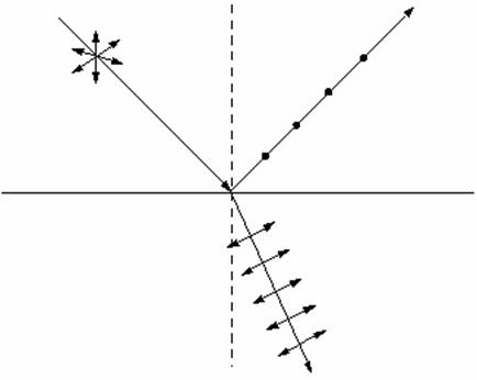
Fig.
1 The use of the refraction and the reflection of light to obtain a polarized
light
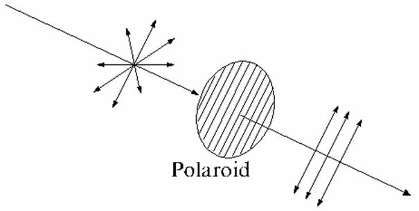
Fig.
2 The use of substances that polarize the light, known as polaroids or polaroid
filters to obtain a polarized light.
A
third method is known double refraction or birefringence. Double refraction
appears in anisotropic crystals, where the velocity of the light propagation, hence
the refractive index too, depend on the direction of propagation in crystal. In
any anisotropic crystal, one or two directions exist, called the optical axes
of the crystal. Along these axes the phenomenon of double refraction does not
exist. An example is the anisotropic crystal of Iceland calcite ( ). This crystal has the property that if an
unpolarized light ray is send perpendicular to the plane surface of a thin
plate of this crystal, along a
direction which differs from the direction of optical axis of the crystal, it
will split into two plane-polarized rays, one that is not deviated from the
normal, called ordinary ray and another that is deviated from the normal, called
extraordinary ray. This phenomenon is called double refraction or birefringence
and was discovered by Erasmus
Bartholinus in 1669. While, in the ordinary ray, the oscillations of the
electric field vector are perendicular to the principal plane of the crystal,
in the extraordinary ray, the oscillations of the electric field vector are in
principal plane of the crystal (the principal plane of the crystal is the plane
determined by direction of the incident ray and direction of the
). This crystal has the property that if an
unpolarized light ray is send perpendicular to the plane surface of a thin
plate of this crystal, along a
direction which differs from the direction of optical axis of the crystal, it
will split into two plane-polarized rays, one that is not deviated from the
normal, called ordinary ray and another that is deviated from the normal, called
extraordinary ray. This phenomenon is called double refraction or birefringence
and was discovered by Erasmus
Bartholinus in 1669. While, in the ordinary ray, the oscillations of the
electric field vector are perendicular to the principal plane of the crystal,
in the extraordinary ray, the oscillations of the electric field vector are in
principal plane of the crystal (the principal plane of the crystal is the plane
determined by direction of the incident ray and direction of the
Fig.
3 Double refraction or birefringence
optical axis of
crystal). If the incident beam is narrow enough and the crystal is thick
enough, the two emergent rays, the ordinary ray and the extraordinary ray, will
be parallel (Fig. 3). While, the ordinary ray propagates through crystal with
the same speed in all directions, the extraordinary ray travels with different
speeds in different directions. The two emergent rays transmitted by the
crystal, the ordinary ray and the extraordinary ray, are very close each other.
In order to separate these rays, hence to obtain polarized light, a Nicol prism
can be used. Let us consider an anisotropic crystal of Iceland calcite This is a
rhombohedron crystal, its longitudinal right section being a parallelogram,
whose length is about three times greater than his width. This
crystal is cut in half along his small diagonal, and the two halves are
cemented together with a material called Canada balsam (Fig. 4). When on his
surface an unpolarized light ray is send, it will split into two plane-polarized
rays, one that is not deviated from the normal, called ordinary ray and
another that is deviated from the normal, called extraordinary ray. Because for
the crystal of Iceland
calcite, the values of the refractive index are  for the ordinary ray
and
for the ordinary ray
and  for the extraordinary
ray, and the refractive index of the Canada balsam is
for the extraordinary
ray, and the refractive index of the Canada balsam is  , result that
  , hence, the ordinary ray will be totally internally
reflected, and
the crystal will transmit only the extraordinary ray, which is a
plane-polarized ray. Therefore, an unpolarized light ray is sending on the
surface of crystal and the light emerging from the crystal is polarized. This device
is called a Nicole
, hence, the ordinary ray will be totally internally
reflected, and
the crystal will transmit only the extraordinary ray, which is a
plane-polarized ray. Therefore, an unpolarized light ray is sending on the
surface of crystal and the light emerging from the crystal is polarized. This device
is called a Nicole

Fig.
4 Nicol prism
prism. This device is also called a polarizer, i.e., a
device used to obtain a plane-polarized light wave. A device used to analyze a
polarized light is called analyzer, for example a rotating Nicole prism can be
used as an analyzer. In order to understand the how the polarizer and analyzer
work, let us consider a mental experiment. Let us assume that a cord oscillates
in the vertical plane and let us suppose that perpendicular to the direction of
oscillations' propagation is placed a plane having a vertical oriented rectangular
opening, placed on the direction of cord's oscillations, whose high is greater
than the cord's oscillations amplitude. Obviously, the cord's oscillations will
pass through this opening beyond the plane. But if perpendicular to the
direction of oscillations' propagation is placed, at a certain distance, a second
plane having a horizontal oriented rectangular opening, the cord's oscillations will not pass. But if this second plane is rotated
with 90 degrees, the rectangular opening will be again in vertical plane and oscillations
will pass through this opening. The
first plane having a vertical oriented rectangular opening can be use as a polarizer.
The second plane having a horizontal oriented rectangular opening can be used
as an analyzer. If we image that many cords exist, oscillating in different
planes, after the first plane only the vertical oriented cord's oscillations
will pass, after the second plane no oscillation will pass, but if this second
plane is rotated with 90 degrees oscillations will pass beyond the plane. An
example of a pair of polarizer and analyzer consisting of polaroid filters is
illustrated in Fig. 5.

Fig.
5. A pair of polarizer and analyzer consisting of polaroid filters
Rotation of the plane of polarization. There
are certain substances, called optically active substances, having the property
of turning of the plane of polarization of a light wave as it travels through
them. This phenomenon was discovered by Arago in 1811 in case of quartz crystals
and is known as natural rotatory polarization, since the presence of an
external magnetic field is not required. In 1815, Biot shown that the liquid solutions of certain substances are
optically active too. An example of an optically active substance is the sugar
solution. A possible application of the polarization of light could be the
determination of the concentration of a sugar solution. When a linear polarized
light ray pass through a tube filled with a sugar solution, the oscillating
plane of the electric field will be rotated with an angle a.
This angle can be determined using an analyzer, hence the concentration will be
given by relation  , where
  is the specific
rotation power (
is the specific
rotation power ( ) and l is the
length of the tube filled with sugar solution.
) and l is the
length of the tube filled with sugar solution.
Magnetic rotation of the plane of
polarization. In 1846 Faraday discovered that even a substance that is not
optically active, but is under the action of an external magnetic field, will
rotate the oscillating plane of the electric field of a linearly-polarized
light ray, if the linearly- polarized light ray travel the substance along a
direction that coincide with the direction of the external magnetic field. The
rotation angle of the oscillating plane of the electric field is determined by
relation:
 (39)
(39)
where R is called the Verdet's constant or the
rotatory magnetic power, l is the
length of the layer of substance traveled and B is magnetic induction in substance. Magnetic rotation of the
plane of polarization is also known as Faraday effect.
Thermal radiation
1. What is the thermal
radiation?
The emission of electromagnetic waves by any body at a temperature
greater than zero Kelvin is called thermal radiation. Obviously, the
intensity of thermal radiation will depend on the temperature of the emitting
body, being higher at high temperatures. At the room temperature the thermal
radiation is emitted by the bodies in the invisible part of the spectrum,
beyond the infrared radiation. When a metal is heated at high temperatures, a
thermal radiation is emitted in the visible part of the spectrum, the light
color varying from red to white, corresponding to the metal's temperature. For
example, incandescent lamps emit yellow light when heated up to 3000 . The thermal radiation is also emitted at low temperatures,
lower than the room temperature, but the thermal energy carried by this
radiation is very small.
. The thermal radiation is also emitted at low temperatures,
lower than the room temperature, but the thermal energy carried by this
radiation is very small.
2. What is the physical mechanism of the thermal radiation's emission?
The emission of
the thermal radiation can be explained as follows: When the temperature of a
body is increassed, the kinetic energy of thermal (chaotic) motion of the atoms of the body, will increasse too.
Therefore, a transition of the atoms in excited states of higher energies can
be realized. The thermal radiation is emitted when the atoms of the body return
from these excited states to other lower energies states. Also, when the atoms
of a body are thermally agitated, their motion will be accelerated. These atoms
contain charges that are therefore thermally accelerated. Hence the thermal
radiation is also emitted by the charged particles, like positive ions or
negative electrons of the body, having an accelerated motion.
3. The spectrum of the thermal radiation.
Any body is a
source of thermal radiation and also absorbs thermal radiation from the
neighbour bodies, so that at equilibrium the energy of emitted radiation will
be equal with that of absorbed radiation. Such a radiation is called the
equilibrium thermal radiation. The spectrum of equilibrium thermal radiation is
a continuum spectrum. The dependence of the spectral emitted power on the
wavelength has a single maximum, whose position and value depend on the
temperature (Fig 1)

Fig. 1
where  is spectral emissive
power of a blackbody, is the wavelength of the thermal radiation and
is spectral emissive
power of a blackbody, is the wavelength of the thermal radiation and  is the temperature of
blackbody.
is the temperature of
blackbody.
The emission and
the absorption of the equilibrium thermal radiation are characterized by the
spectral emissive power and respectively by the spectral absorption power. The
energy of the emitted thermal radiation per unit time per unit area of
radiating surface of a body, at temperature T, in all
directions, in the frequency interval from n to n+dn is
called spectral emissive power .This is given by
 (1)
(1)
where dW is the energy of
the emitted thermal radiation per unit time per unit area of radiating surface
in the frequency interval from n to n+dn.
The
energy of the emitted thermal radiation per unit time per unit area of
radiating surface of a body, at temperature T, in all directions, in the frequency interval
from 0 to  , that is for all the frequencies, is called total
emissive power . It is denoted by
, that is for all the frequencies, is called total
emissive power . It is denoted by  is defined as follows
 (2)
(2)
The quantity
describing the capacity of a body to absorb the incident radiation at a given
frequency is called spectral absorption power. It is denoted by , and is defined as
follows:
, and is defined as
follows:
 (3)
(3)
Therefore, the spectral absorption
power represents the fraction of the energy dWinc, delivered
in unit time to unit area of the body surface by incident electromagnetic waves
with frequencies from n to n+dn, that is absorbed by the body.
The fraction of
the energy dWinc, delivered in unit time to unit area of the
body surface by incident electromagnetic waves with frequencies from 0 to , that is for all the frequencies, that is absorbed by the
body is called total absorption power
. It is denoted by AT and
is defined as follows
 (4)
(4)
The blackbody is
an ideal body that can absorb all the radiations falling on him. By example, a
small orifice on the surface of a sphere covered on interior with soot black,
can be considered, in a first approximation, as a blackbody. When a ray of
light goes into the sphere through this orifice, it is reflected many times and
also partly absorbed by the walls of the sphere, so that the probability to go
out is very close to zero.
If  is spectral emissive
power of a blackbody, then total emissive power of a black body, eT, will be
is spectral emissive
power of a blackbody, then total emissive power of a black body, eT, will be
 (5)
(5)
Because
, (6)
and taking into account that spectral
emissive power of a blackbody is also denoted by, then total emissive power of a blackbody, eT, can also be written as
 (7)
(7)
Laws of the blackbody radiation
1. Kirchhoff Law
The Kirchhoff's
law of the thermal radiation, established by Kirchhoff in 1859, states that the ratio between the spectral
absorption power and spectral emissive power, at the same temperature and
for the same frequency of the thermal radiation, is the same for all bodies,
being an universal function of temperature and radiation's frequency. This
ratio is equal to the spectral emissive power of a blackbody at that same
temperature. The the spectral
absorption power of a blackbody being
equal to the unity.
The
Kirchhoff radiation law may be written as
 (1)
(1)
Since
for the real bodies  , result that
  . Therefore the spectral emissive power, of a blackbody is
greater than of any bodie at the same
temperature, T.
. Therefore the spectral emissive power, of a blackbody is
greater than of any bodie at the same
temperature, T.
2. Stefan-Boltzmann Law
In 1879, Josef
Stefan, physicist professor at Viena
University, has studied
experimentally the dependence of the energy of the thermal radiation emitted by
a heated body on temperature. He finds that the total thermal energy emitted
per unit time per unit area of radiating surface of a body is proportional to
the four power of its absolute temperature. The empirical law discovered by Stefan was not confirmed by the
subsequent measurements. The Stefan empirical law was corrected by Boltzmann, a
former student of Stefan. In 1884 Boltzmann, using the laws of thermodynamics,
has theoretically demonstrated that total thermal energy emitted per unit time
per unit area of radiating surface of a blackbody is proportional to the four
power of its absolute temperature. Therefore, the empiric law discovered by
Stefan was not valid for all bodies but only for the blackbody. Mathematically,
the Stefan-Boltzmann law, has the form
 (2)
(2)
where s, is a constant, called
the universal Stefan-Boltzmann
constant. For a blackbody, the experimentally established value of this
constant is
 . (3)
. (3)
3. Wien's Displacement Law
Before 1880, it was known, on the evidence of
the experimentally obtained curves of the blackbody radiation of Fig. 2, that
the dependence of the spectral emitted power on the wavelength has a
single maximum, whose position and value depend on the temperature.
In
1893, using the principles of thermodynamics, Wien established a law, known
today as Wien's Displacement law. He
has found that as the temperature of
any blackbody increases, the curve retains its general shape, but the maximum
of the curve increases and the maximum
of the curve shifts to smaller wavelengths. Mathematically, this law has the
form
 (4)
(4)
where T is the temperature,  is the wavlength corresponding to the maximum
of the spectral emitted power and
b is a constant whose value
is b=2.898 10-3 m K.
is the wavlength corresponding to the maximum
of the spectral emitted power and
b is a constant whose value
is b=2.898 10-3 m K.
Wien's Displacement law can be used
to determine the absolute temperature of a blackbody. For example, the sun has
a spectral distribution of the thermal radiation is very close to that of a
blackbody, the maximum of the spectral curve having the wavelength equal to 470
nm. Using Wien's Displacement law on obtain for the absolute temperature at the
surfacee of the sun a value approximative equal to 6200 K.
4. Wien Law
It was known that the radiation
spectrum of a blackbody is a continuum spectrum. The form of this spectrum was
also known but the analytical dependence of the spectral emitted power,, on the wavelength and on temperature was unknown. This analytical dependence was investigated first
in 1887 by the Russian physicist V. Michelson. Then in 1896, the German
physicist Wilhelm Wien, found, using both the experimental data concerning the
form of this spectrum and also the laws of thermodynamics and electromagnetism,
that spectral emissive power of a
blackbody can be written as follows:
 (6)
(6)
where l
is the wavelength, T is the absolute temperature, e is the base of the natural logarithms and  and
and  are two adjustment
constants. Wien Law is an
empirical law, i.e. for certain values of the constants and , and in the range of small wavelengths, this law
offers a rather good fit to the experimental data.
are two adjustment
constants. Wien Law is an
empirical law, i.e. for certain values of the constants and , and in the range of small wavelengths, this law
offers a rather good fit to the experimental data.
Fig. 2
The energy distribution in the radiation spectrum of a blackbody. The
dependence of the spectral emitted power on the wavelength and on the
temperature.
Wien Law can be written also
 (7)
(7)
from (5) and (7) result
 , (8)
, (8)
or
 . (9)
. (9)
or
 (10)
(10)
Taking into account that
 (11)
(11)
and
 (12)
(12)
on obtain
 . (13)
Substituting (13) into (10)
result
 (14)
(14)
Substituting (6) into (14) and
using (11), on obtain
 .
.
Therefore, the Wien law can be
written as
 (15)
(15)
where b1 and b2
are two constant.
It is easy to show that spectral emissive power, , has the form
 (16)
(16)
where  is the spectral energy
density of thermal radiation, also denoted by
is the spectral energy
density of thermal radiation, also denoted by . Energy density of the thermal radiation is
From (15) and (16) result that
Wien law can also be written as
 (17)
(17)
where  and
and  are two constants.
5. Rayleigh-Jeans Law
In 1900 the British physicist Lord Rayleigh (its true name is John
William Strutt), starting from a theorem of statistical mechanics concerning the law of uniform distribution of the
kinetic energy among degrees of freedom, theoretically established an
expression for the dependence of spectral
emissive power of a blackbody on wavelength and temperature. Rayleigh found that, in the range of long
wavelengths, the expression  leads to a rather
good agreement with the experimental data. Later in 1905, James Jeans has
derived the expresions for the constants of proportionality appearing in
Rayleigh's formula. Therefore the Rayleigh-Jeans
law has the form
leads to a rather
good agreement with the experimental data. Later in 1905, James Jeans has
derived the expresions for the constants of proportionality appearing in
Rayleigh's formula. Therefore the Rayleigh-Jeans
law has the form
 (18)
(18)
Rayleigh-Jeans law can also be written
as
(19)
Substituting
(18) into (14) and using (11), on obtain
 . (20)
Hence,
Rayleigh-Jeans law can be written as
 . (21)
Taking intoo
acount that
(22)
and using (21)
and (22) result that Rayleigh-Jeans law can be written as
 (23)
(23)
This is another
form of Rayleigh-Jeans law. While this law fits well the experimental data in
the range of long wavelengths, in the range of short wavelengths this law leads
to disagreement with the experimental
data. This disagreement is known as ultraviolet catastrophe, since at short
wavelengths or high frequencies both and increase toward
infinity.
Both Wien laws
and Rayleigh-Jeans law were just attempts to derive on the basis of classical
physics the analytical dependence of the spectral emitted power of a blackbody
on wavelength and temperature. Since these attempts are only partly successful
show that in classical physics a good description of the spectral distribution
of a blackbody's thermal radiation can not be obtained.
6. Planck's Formula
 (32)
(32)
The equilibrium
condition is
 (33)
(33)
Let us assume
that  is the probability of
a stimulated transition of an atom in unit time from the energy level
is the probability of
a stimulated transition of an atom in unit time from the energy level  to the level
  , and let us assume
that
, and let us assume
that is the probability of the reverse transition. The probability of stimulated transitions
is proportional to the spectral density
of energy of the electromagnetic
field inducing the transition. Hence, we can write
is the probability of the reverse transition. The probability of stimulated transitions
is proportional to the spectral density
of energy of the electromagnetic
field inducing the transition. Hence, we can write
 (34)
(34)
and
 (35)
(35)
where the coefficients  and
and  are known as
Einstein's coefficients.
are known as
Einstein's coefficients.
Therefore,
the number of the atoms that perform in unit time a stimulated transition m n is given by
 (36)
(36)
the number of the atoms that perform in unit
time a stimulated transition n m is
 (37)
(37)
Substituting
(32), (36) and (37) into (2.33) on obtain (Fig. 3)
 (38)
(38)
Fig.
3
or
 (39)
(39)
Since, for T we
have rnT , result that =. Hence, the relation (39) becomes
 (40)
(40)
Taking into account (28) and (29) the
relation (40) becomes
 (41)
(41)
The coefficient  , will be determined from condition that the expression (41),
at low frequencies, must coincide with Rayleigh-James formula. For small
frequencies, when
, will be determined from condition that the expression (41),
at low frequencies, must coincide with Rayleigh-James formula. For small
frequencies, when
 (42)
(42)
we can write
 (43)
(43)
Substituting (43) into (41), on obtain
 (44)
(44)
On the other side, according to Rayleigh-James law, we have
(45)
since
(44) and (45) must coincide, we get
 (46)
(46)
Substituting the coefficient given by (46) into
(41) on obtain Planck's formula
 (47)
(47)
Applications.
a) It is easy to
see that Wien law can be obtained from Planck's formula, in the particular case
of high frequencies. In this case
 (48)
(48)
hence, we can
approximately write
 (49)
(49)
Substituting
(49) into (47) we get Wien law:
 (50)
(50)
b)
Stefan-Boltzmann law can be derived from Planck's formula. Let us start from
relation
(51)
Substituting
(47) into (51) on obtain
or
 (52)
(52)
The total
emissive power will be
 (53)
(53)
Denoting
 (54)
(54)
we can write
 (55)
(55)
and
 (56)
(56)
Substituting
(55) and (56) into (53) result
 (57)
(57)
Since
 (58)
(58)
on obtain
 (59)
(59)
or
 (60)
(60)
Therefore, the
Stefan-Boltzmann law was derived
(61)
where
 (62)
(62)
is the
Stefan-Boltzmann's constant.
c) Wien's displacement law can be
derived from Planck's formula. Let us start from the total emissive power of a
blackbody
 (63)
(63)
Using (63) we
can write
 (64)
(64)
or
 (65)
(65)
 (66)
(66)
then substituting (66) into (65) on
obtain
 (67)
(67)
Substituting  given by Planck's
formula (47) into (67) on can write
given by Planck's
formula (47) into (67) on can write
or
 (68)
(68)
The wavelength corresponding to the
maximum of the function  , is determined from condition
 (69)
(69)
Denoting
 (70)
(70)
on can write
 (71)
(71)
then, substituting (71) into (68)
on obtain
 (72)
(72)
Hence, the condition
 (73)
(73)
can be written as
 (74)
(74)
or
 (75)
(75)
hence, weget the equation
 (76)
(76)
whose approximative solution is
 (77)
(77)
Using (70) on obtain
 (78)
(78)
Therefore, Wien's displacement law
can be written as
 (79)
(79)
where
 (80)
(80)
is Wien's constant.